


Courses by Software
Courses by Semester
Courses by Domain
Tool-focused Courses
Machine learning
POPULAR COURSES
Success Stories

Week 3 Challenge : CFD meshing on Turbocharger
QUESTION -For the given Turbocharger geometry, resolve all the geometrical errors, assign PIDs and perform surface mesh & volumetric mesh according to the given conditions. Write down a detailed report mentioning the entire process. Also, include the concepts you learned. Final Geometry File: https://drive.google.com/file/d/17RLvI5LIRcrQ3-h0U5N6fe_h62oQ0P4D/view?usp=sharingANSWER…
Bhavesh Kumbhare
updated on 28 Sep 2022


QUESTION -
For the given Turbocharger geometry, resolve all the geometrical errors, assign PIDs and perform surface mesh & volumetric mesh according to the given conditions. Write down a detailed report mentioning the entire process. Also, include the concepts you learned.
Final Geometry File: https://drive.google.com/file/d/17RLvI5LIRcrQ3-h0U5N6fe_h62oQ0P4D/view?usp=sharing
ANSWER -
A Turbocharger is a forced induction device powered by exhaust gas flow. It compresses the intake gas, forcing more air into the engine and producing more power for the same displacement.
Aim -
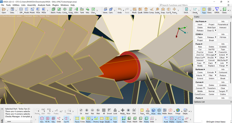
To set the target length & mesh the given model according to the conditions mentioned in the ANSA pre-processor. ANSA is a popular computer-aided engineering tool for CFD and Finite Element Analysis in the automobile sector.
Procedure -
We will follow three major procedures to accomplish the challenge, namely;
Resolving Geometrical Errors
Assigning PIDs
Mesh Generation
Steps -
You are in the "Topo Deck" by default. Import the Geometry. Turn the geometry to "Shadow display" mode from the "Wireframe display" mode so as to perform the desired operations on it.
1. Resolving Geometrical Errors -
Check all the errors in the given geometry;
Tool Bar > Checks Geometry > Geometry_Checks > Execute 
Here you will find all the errors that your geometry contains.
Before resolving the errors, we can find that the turbo casing has an excess part that overlaps the actual casing. We will delete that particular part permanently. 
Using various tools under "Module Buttons Group" we need to resolve all the errors in our geometry. 
The "Transform" module button under the "Curves" module helps to create a temporary boundary. This tool actually replicates a particular curve between two nearby hot points.
We will use this tool to set a temporary boundary to ease the resolution of this error.
Topo Deck > Curves > Transform > select a particular cone > middle click > select two hot points
The "Loop" option will not work for curves as they are temporary boundaries.
Curves can be deleted after the purpose is fulfilled. 

Here, there is no exact boundary defined and hence, we may find some intersection errors.
The "Intersect" module button under the "Faces" module forces the geometry to create proper boundaries or edges.
Face Module > Intersect > First > select first two faces connected > middle click > select other two faces connected > middle click 
Now, we will be asked to 'Keep' or 'Delete' some particular highlighted faces one by one. Delete the faces which aren't necessary and keep the faces that are necessary for the geometry.
Now, an exact boundary has been defined so that no intersection error occurs. 


Now, we need to insert a symmetrical face here in order to resolve this error. 
Insert additional hot points in the middle of both the end corners as shown. 
To insert a symmetrical face:
Tool Bar > Transform > Copy > Entities > select the faces > middle click > Symmetry > click three hot points at one of the corners > middle click > OK > Finish
Thus, a symmetrical face has been created.
Let's have a Geometry Check again.
Here, all the geometry errors have been resolved. Only nine intersection errors are left. We need to clear them all one by one. 

Here, we will find some Triple Cons which cannot be avoided in geometry.
The "Topo" module under the "Faces" module button helps to auto-fix errors that aren't much significant in the geometry. It joins the faces which are not joined properly after we perform error clean-up.
Note - To perform volume mesh all the intersection errors, along with geometric errors, need to be resolved. However, the surface mesh can be generated even though intersection errors aren't cleared. To perform surface mesh at least geometric errors should be cleared.
Also, in ANSA Pre-processor, while performing volume mesh, in order to generate a single mesh, we need to delete out all the parts or faces that separate a single geometry and divide it into several parts.
Let's resolve all the intersection errors displayed in the previous geometric check.
Perform a "Topo" over the entire geometry. Some triple cons have been generated which need to be eliminated. 
We completed eliminating all the triple cones by internal inspection of the geometry.

Here, we find that an excess part of the pink shaft has entered the yellow shaft which is causing an intersection error. We need to delete that excess part of the pink shaft. 
Cons > Project > select double cons of the pink shaft at the middle > middle click > select both the faces of the pink shaft > middle click
We separated the pink shaft into two parts by projecting the boundary of the pink shaft over the pink shaft. Thus, the excess part has been deleted. 
Let's have a geometry check again. We have resolved five intersection errors and only four are left.


All the intersection errors have been resolved. Let's move toward assigning PIDs. Here, PIDs are already assigned, we just need to rename them according to the given components and we will delete all the unnecessary PIDs using the "Compress" tool. 
Blade Stage 1
Blade Stage 2
Impeller
Shaft Rotor
Turbo Casing
Compressor Casing
Inlet Casing Cover 
Thus, we have assigned PIDs to various components of the turbocharger. 
Now, our geometry is ready to generate the mesh. We need to perform surface mesh as well as volume mesh over the geometry.
Note - Even though it is not asked in the question always close the geometry. Because the surface mesh is a prerequisite for volumetric mesh. Surface mesh can be generated without closing all the open surfaces of the geometry, however, volume mesh cannot be generated with open surfaces. A closed volume is required to successfully accomplish and generate volume mesh.
It is always advisable to close all the open surfaces in geometry before generating mesh because, in the future, it may happen that one requires volumetric mesh over the same geometry. If we change the geometry after the surface mesh is generated, errors will occur and mesh will get erased over the corrected parts. Thus, the final results would be affected.
Thus, we will close all the open faces in our geometry. 

Note - We need not assign new PIDs for these newly generated surfaces. It will automatically get assigned to the respective component's PID.
Surface Mesh -
Click "Classic Mesh"
Target lengths for mesh specified for various components are -
Blade Stage 1 - 1 mm
Blade Stage 2 - 1 mm
Impeller - 2 mm
Shaft Rotor - 1 mm
Turbo Casing - 5 mm
Compressor Casing - 5 mm
Inlet Casing Cover - 5 mm
Here, we can either mesh each component one after another, or else we may mesh components with the same target length at once. When we mesh the components using either of the two ways, we may find that each individual meshing has been generated very properly according to the given target lengths.
However, when we look at mesh generated over the entire geometry, we may find some unmeshed surfaces. These unmeshed surfaces are generated due to the varying target lengths of each individual component.
These unmeshed surfaces are generated at the perimeters of the components of different target lengths.
To avoid this we have two methods;
1. As soon as we finish the mesh generation of the entire geometry and find some unmeshed surfaces, we need to use the "Free" module button in the "Mesh Generation" module button group.
Classic Mesh > Mesh Generation > Free > Visible
2. As soon as we finish mesh generation of each component(s) with the same target length, use the "Freeze/Unfreeze" module button in the "Macros" module button group to freeze the mesh generated over the selected geometry so that it won't be erased or deleted when we mesh the other components.
Classic Mesh > Macros > Freeze > Left click > select the visible geometry
Repeat this tool after mesh generation of every component(s). After finishing mesh generation all the components use the same "Freeze/Unfreeze" module button in order to further process the geometry.
Classic Mesh > Macros > Freeze > Right click > select the visible geometry
Among the two methods, the former is a shortcut tool to fix unmeshed surfaces. However, the latter method is a professional way to generate mesh over the components with varying target lengths.
To generate mesh, we need to follow three steps:
Click "Mesh Parameters" in the Toolbar. Under the "Basic" menu, select mesh type as "CFD Mesh" & element type as "Tria". Enter the minimum target length and maximum target length. Click OK.
| Sr. No. | Component(s) | Given Target Length | Minimum Target Length assigned | Maximum Target Length assigned |
| 1) | Turbo Casing, Compressor Casing & Inlet Casing Cover | 5 mm | 6 mm | 4 mm |
| 2) | Impeller | 2 mm | 3 mm | 1 mm |
| 3) | Shaft Rotor, Blade Stage 1 & Blade Stage 2 | 1 mm | 1.4 mm | 0.6 mm |
Here, we used CFD mesh instead of General mesh because the former gives more accurate results. One can select General mesh as well, there will be no error in the final results.
Perimeters Module > Spacing > Auto CFD > Perimeters > Select entire geometry > middle click > OK > Macros > Select entire geometry > middle click > OK
Mesh Generation Module > CFD > Visible 


Thus, Surface mesh generation has been completed.
Volume Mesh -
Click "Volume Mesh"
In volume mesh, we are focusing on the 'internal flow analysis' and we only need the internal volume of our geometry.
Note - We can include the external volume too, however it will increase our computational time and cost. Hence, it is practically efficient to only include the internal volume.
Hence, we will delete all the external volumes of our geometry.
Volumes Module Group > Define Module > OK
Now, a box will appear with all the volumes detected in our geometry. Simply, we need to keep the internal volumes and delete all the external volumes which, as of now, are not necessary for us. 

Change the Volume Type of three internal volumes from undefined to 'Tetra CFD' as;
Double click over a particular volume name > Type > select Map > OK
Long press over a particular volume name > select Tetra CFD
Remesh all the internal volumes.
Thus, Volume mesh generation has been completed. 
To see the volume mesh through a cut section;
Tool Bar > Cut Plane > New > Default XY (or choose the plane you want) > Click on any point on our geometry from which you want a cut > Parts > New > click Part > click on the new part generated > double click > OK 

Learning Outcomes - Acquired knowledge of various new tools and how to use them to execute operations on given geometry. Volume mesh was introduced newly.
Result - Geometry was modified according to given conditions and proper meshing was done.
Conclusion - A detailed report of the entire surface meshing and volume meshing processes was mentioned.
Leave a comment
Thanks for choosing to leave a comment. Please keep in mind that all the comments are moderated as per our comment policy, and your email will not be published for privacy reasons. Please leave a personal & meaningful conversation.
Other comments...
Be the first to add a comment
Read more Projects by Bhavesh Kumbhare (15)
Heat Transfer analysis using Battery Thermal Management System (BTMS) for Lithium ion battery module used in Electronic Vehicles using Ansys Fluent
Problem Statement AIM - A simulation for heat transfer analysis for the cylindrical Lithium ion battery, with heat generation boundary condition, is to be performed using Ansys Fluent. INTRODUCTION -Electric vehicles charge their batteries with electricity rather than using fossil fuels such as gasoline or diesel. Electric…

19 Jun 2023 11:58 AM IST
Week 9 - Parametric study on Gate valve.
AIM -A steady-state simulation for the parametric study of flow through a gate valve is to be performed in Ansys Fluent.INTRODUCTION & THEORY - Gate Valve -The most common type of valve in water supply systems is a gate valve. It is a linear-motion isolation valve with the ability to stop or allow flow. The closure…
23 Jan 2023 02:22 PM IST
Week 3 - External flow simulation over an Ahmed body.
AIM -A simulation for external flow analysis over an Ahmed body is to be carried out for the velocity of 25 m/sec with the default air properties in Ansys fluent. INTRODUCTION - It is asked to compute an external flow simulation over an Ahmed body using air, with a 25 m/sec velocity, as working fluid. The geometry…
10 Jan 2023 09:00 AM IST
Week 6 - CHT Analysis on a Graphics card
AIM - A steady-state simulation for Conjugate Heat Transfer (CHT) analysis of Graphics Card to be performed using Ansys Fluent. INTRODUCTION - Conjugate Heat Transfer (CHT) is the exchange of thermal energy at the interfaces of solid and fluid domains to transfer heat. That is, it includes both conduction and convection…
06 Jan 2023 08:22 AM IST
Related Courses


Skill-Lync offers industry relevant advanced engineering courses for engineering students by partnering with industry experts.


Our Company

4th Floor, BLOCK-B, Velachery - Tambaram Main Rd, Ram Nagar South, Madipakkam, Chennai, Tamil Nadu 600042.

Top Individual Courses
Top PG Programs
Skill-Lync Plus
Trending Blogs
© 2025 Skill-Lync Inc. All Rights Reserved.