


Courses by Software
Courses by Semester
Courses by Domain
Tool-focused Courses
Machine learning
POPULAR COURSES
Success Stories

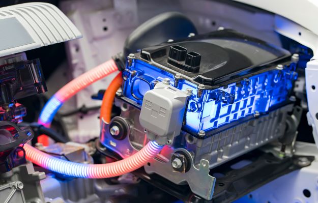
Heat Transfer analysis using Battery Thermal Management System (BTMS) for Lithium ion battery module used in Electronic Vehicles using Ansys Fluent
Problem Statement AIM - A simulation for heat transfer analysis for the cylindrical Lithium ion battery, with heat generation boundary condition, is to be performed using Ansys Fluent. INTRODUCTION -Electric vehicles charge their batteries with electricity rather than using fossil fuels such as gasoline or diesel. Electric…
Bhavesh Kumbhare
updated on 19 Jun 2023


AIM -
A simulation for heat transfer analysis for the cylindrical Lithium ion battery, with heat generation boundary condition, is to be performed using Ansys Fluent.
INTRODUCTION -
Electric vehicles charge their batteries with electricity rather than using fossil fuels such as gasoline or diesel. Electric vehicles are more efficient, and when combined with the cost of electricity, charging an electric vehicle is less expensive than filling up with gasoline or diesel for your travel needs. An electric vehicle (EV) is one that runs on electricity rather than an internal combustion engine. Power is provided by the motor in this type of vehicle, and the battery serves as a resource to store the energy required to generate enough power for the motor.
Because electric vehicles have fewer moving parts than internal combustion vehicles, they require less maintenance. Electric vehicles require less maintenance than conventional gasoline or diesel vehicles. As a result, the annual cost of operating an electric vehicle is significantly lower.
 |
THEORY -
Battery in Electric Vehicle (EV) -
The lithium-ion batteries successfully dominated the market after the lead-acid batteries. The majority of electric vehicles from the current generation have lithium-ion batteries. These are more dense in nature and based on new technology. Although the exact chemistry frequently differs from that of consumer electronics batteries, the majority of all-electric and plug-in hybrid vehicles on the road today use lithium-ion batteries. They also have a good high-temperature performance, a high power-to-weight ratio, high energy efficiency, and low self-discharge.
 |
Working Principle of Lithium-ion Batteries -
The components of a battery are an anode, a cathode, a separator, an electrolyte, and two current collectors (positive and negative). Lithium is kept in storage by the anode and cathode. Through the separator, the electrolyte transports lithium ions that are positively charged from the anode to the cathode and vice versa. The movement of the lithium ions in the anode releases free electrons, which charges the positive current collector. The electrical current then travels from the positive current collector through a powered device (such as a computer or cell phone) to the negative current collector. Inside the battery, the separator prevents the flow of electrons. The anode releases lithium ions to the cathode as the battery discharges and produces an electric current, which causes a flow of electrons from one side to the other. The opposite occurs when the device is plugged in lithium ions are given off by the cathode and received by the anode.
 |
C-Rate of Battery -
C-rate is a unit used to measure the speed at which a battery is charged or discharged. It is the charge or discharge current in Amps divided by the cell capacity in Ampere-hours. A 1C rate means that the battery is charged or discharged in one hour. A C-rate higher than 1C means a faster charge or discharge. The C-rate is important to know because the available stored energy depends on the speed of the charge and discharge currents.
Battery Thermal Management System In EV -
The Battery Thermal Management System (BTMS) uses thermoelectric cooling & forced air cooling. In order to dissipate the heat produced by the battery during operation, the fluid coolant comes into direct contact with the battery. The main goal of the BTMS is to control the battery's cell temperature in order to prolong the battery's life. To prevent a continuous temperature rise, the battery thermal management system must dissipate the heat produced during operation. The optimal operating temperature for battery life is determined by a number of ageing mechanisms with diverse temperature dependences, necessitating temperature regulation by a BTMS.
The major classification of BTMS corresponds to systems with and without fluid in motion. The first type is known as active BTMS, while the second is known as passive BTMS.
 |
Thermal Runaway of Battery in EV -
Thermal runaway refers to a process that is accelerated by higher temperatures, releasing energy that raises the temperature even higher. Thermal runaway occurs when an increase in temperature changes the conditions in such a way that it causes another increase in temperature, often with disastrous results. When the temperature inside one of the battery cells rapidly rises, a dangerous condition occurs.
In EVs, thermal runaway is the condition in which a battery catches fire due to rapid heat propagation from one damaged cell to another cell. The desired operating temperature range of the battery is 15° C to 35° C. Thermal runaway can occur in less than 10 seconds and the heat generated can be on the order of 107 W/m3.
 |
 |
SOLVING & MODELLING APPROACH -
For each CFD simulation, the procedures to be followed are as follows:
• Problem finding
• Pre-processing
• Solver or Processing
• Post-processing
A 4 X 2 battery pack with cylindrical batteries that are 18 mm in diameter and 65 mm in height is what the problem statement asks you to build. Additionally, it is necessary to build an enclosure that will serve as the computational domain for all simulations. The working fluid for cooling the batteries is air, with an inlet temperature of 26° C. The lithium ion battery is assumed to have a 3.6 V voltage and a 2.2 A capacity.
A battery pack with only 8 batteries is used so as not to exceed the mesh element size restrictions.
The properties of any material that must be assigned for any heat transfer analysis problem are its density (ρ), specific heat capacity (cp), and thermal conductivity (k).
In this simulation, we assigned the convection wall as polystyrene material, the battery itself is made up of lithium and aluminium is used in the peripheral part of battery.
The following are the essential properties of the materials listed above taken from some literature;
|
Material |
Density [kg/m³] |
Specific Heat Capacity [J/kg K] |
Thermal Conductivity [W/m K] |
|
Lithium |
2722 |
1200 |
0.2 |
|
Polystyrene |
100 |
600 |
0.1 |
|
Aluminum |
2719 |
871 |
202.4 |
According to the problem statement, the separation between the batteries in the battery pack system is initially assumed to be 2 mm. A mesh independent study with a 3 m/sec inlet velocity will be conducted to determine the optimum mesh element size for future cases. Later, the inlet velocity of air is varied to 5 m/sec and 10 m/sec based on the mesh independent study. Based on the previous results, the space between the batteries is increased to 4 mm and 6 mm by selecting any one case of inlet velocity. Thus, in total, seven simulations will be run. Finally, all of the results must be summarised in a tabular format, and conclusions must be drawn.
|
Case No. |
Element Mesh Size (mm) |
Inlet Velocity (m/sec) |
Separation Distance between batteries (mm) |
|
1 |
8 |
3 |
2 |
|
2 |
5 |
3 |
2 |
|
3 |
2.5 |
3 |
2 |
|
4 |
8 |
5 |
2 |
|
5 |
8 |
10 |
2 |
|
6 |
8 |
10 |
4 |
|
7 |
8 |
10 |
6 |
In SpaceClaim, a battery pack system (4 X 2) will be created, along with an enclosure, using the various tools. In the Mesh file, mesh will be generated over the entire arrangement with inflation layers around the batteries. Later, various components will be assigned under the Named Selection. Simulations for seven cases with relevant solver settings will be run and results will be plotted on the forms of plots and contours in the post processing stage. Later, conclusions will be made based on the results calculated and will be presented in tabular form.
PRE-PROCESSING -
Right-click on Geometry in the Project Schematic of the Workbench window to launch SpaceClaim. First, turn on the sketch plane in the XY axis in SpaceClaim. Create a circle with a diameter of 18 mm, and then extrude the circle (2D surface) into a cylinder (3D) with a height of 65 mm using the "Pull" tool in the "Design" tab. We will now create multiple cylindrical batteries using the "Linear Pattern" tool (4 X 2 = 8 Batteries).
Design tab > Linear Pattern tool > Structure Outline > Pattern Type = Two-dimensional > X Count = 4 > Y Count = 2 > X Pitch = 20 mm > Y Pitch = 20 mm
Give the desired directions using arrows to create a 4 X 2 battery pack configuration.
 |
 |
 |
_1675497933.png) |
In order to run the simulation and draw conclusions, we will now prepare an enclosure for the battery pack system using the "Enclosure" tool located under the "Prepare" tab. The figure below displays the measurements that were made.
 |
 |
The 'Share Topology' tool, located under the 'Workbench' tab, will now be enabled in order to share mesh information between the fluid and battery systems. In the structure outline, Preserve instances must be disabled. Exit the SpaceClaim.
Later, in the Workbench window's Project Schematic, right-click Mesh.
Update the mesh, then assign the following components using the Named Selection:
• Inlet
• Outlet
• Convection Wall
• Battery System
• Fluid Domain
Due to their exposure to outside factors, the side walls of the enclosure are designated as the Convection Wall. The convective heat transfer coefficient (h), which should be low for natural convection, will be 5 W/m²K.
In order to properly capture the flow variables at the surface of batteries, inflation layers must be added. Under the Mesh outline structure, we will use the "Program Controlled" method for this.
 |
 |
Note that the mesh outline structure's "Program Controlled" method automatically locates the interior surfaces and generates the appropriate inflation layers. In this instance, the battery walls create inflation layers.
SOLVER -
Right-click Setup in the Project Schematic section of the Workbench window.
The flow that is taken into account in this simulation corresponds to the flow through the duct. We are aware that there may be some turbulence close to the battery walls even though the flow is laminar. As a result, K omega SST model was used as the viscous model rather than a laminar model.
Set the solver settings as follows:
|
Fluent Setup |
|||
|
Sr. No. |
Setup |
Command |
|
|
1 |
Solver Type |
Pressure based |
|
|
2 |
Solver Time |
Steady State |
|
|
3 |
Energy Equation |
ON |
|
|
4 |
Viscous Model |
K omega SST |
|
|
5 |
Material |
Fluid - Air |
|
|
Solid - Lithium, Polystyrene & Aluminium |
|||
|
6 |
Cell Zone |
Battery |
Type - Solid; Material - Lithium |
|
Source Term = 1; Energy = 48750 W/m3 |
|||
|
7 |
Boundary Condition |
Convection Wall - 5 W/m²K; 26 °C; Polystyrene |
|
|
Inlet - Velocity Boundary Condition |
|||
|
Outlet - Pressure Boundary Condition |
|||
A report was created using the "Report Definitions" tool to calculate the battery system's average temperature, maximum temperature, and heat transfer coefficient.
Initialising the solver settings, convergence was reached after a predetermined number of iterations for each of the seven cases.
In the first three cases, reducing the default mesh element size a mesh independent study was conducted to determine the ideal mesh size for carrying out subsequent simulations with different inlet velocities and different separation distances between the batteries. The independent mesh study's findings are as follows:

As is evident, the results are not significantly affected by the difference between refined mesh (mesh element size = 2.5 mm) and coarse mesh (mesh element size = 8 mm). Therefore, we will continue to use 8 mm mesh element size for future cases.
With an 8 mm mesh element size, which is considered to be the ideal mesh size, we will now increase the inlet velocity for two more cases to 5 m/sec and 10 m/sec, and the results will be calculated.
In order to reduce the project's computational time, the values for the mesh element size, inlet velocity, average temperature, maximum temperature, and the heat transfer coefficient of the battery pack were parameterized.
The separation distance between the batteries in the battery pack must now be increased from 2 mm to 4 mm and 6 mm. As a result, simulations for two additional individual cases with batteries spaced 2 mm and 4 mm apart will be run with a mesh element size of 8 mm and an inlet velocity of 10 m/sec.
From the last two cases, it can be inferred that the former case - with a 4 mm separation distance between the batteries - is preferable in terms of outcomes to the latter case - with a 6 mm separation distance. In order to determine the difference and make broad conclusions about the simulation study as a whole, we will compare the case 1 and case 6 parameters.
|
Plots |
Case 1 |
Case 6 |
|
Scaled Residuals |
|
|
|
Average Temperature |
|
|
|
Maximum Temperature |
|
|
|
Heat Transfer Coefficient |
|
|


POST-PROCESSING -
Right-click Result in the Project Schematic section of the Workbench window.
Temperature, velocity, and velocity vector contours were plotted and saved over a plane perpendicular to the fluid flow.
RESULTS -
|
Contours |
Case 1 |
Case 6 |
|
Temperature |
|
|
|
Velocity |
|
|
|
Velocity Vector |
|
|


Animations for the temperature distribution and velocity vector for the Case 6 is plotted as:
|
Temperature Distribution |
Velocity Vector |
|
|
|


CONCLUSION -
|
Case No. |
Element Mesh Size (mm) |
Inlet Velocity (m/sec) |
Separation Distance between batteries (mm) |
Cell Count (Lacs) |
Average Temperature of Battery (°C) |
Maximum Temperature of Battery (°C) |
Heat Transfer Coefficient of Battery (W/m²K) |
|
1 |
8 |
3 |
2 |
1.54 |
31.35 |
39.53 |
- 12.03 |
|
2 |
5 |
3 |
2 |
1.67 |
31.18 |
38.94 |
- 12.14 |
|
3 |
2.5 |
3 |
2 |
3.63 |
30.68 |
37.02 |
- 12.46 |
|
4 |
8 |
5 |
2 |
1.54 |
29.07 |
33.09 |
- 13.69 |
|
5 |
8 |
10 |
2 |
1.54 |
27.82 |
30.62 |
- 14.92 |
|
6 |
8 |
10 |
4 |
1.59 |
27.76 |
30.55 |
- 14.97 |
|
7 |
8 |
10 |
6 |
1.74 |
27.74 |
30.5 |
- 15 |
A few conclusions about the study can be drawn after operating the simulation for all seven cases;
• A fairly decent temperature decrease was seen as the inlet velocity was increased for cases where the distance between the batteries was 2 mm.
• Similarly, when discussing the inlet velocity alone as a parameter, we can observe a significant temperature difference when we increase the inlet velocity from 3 m/s to 10 m/s.
• As the inlet velocity increases, the battery pack's heat transfer coefficient value also rises. The negative sign here indicates that the batteries are dissipating the heat, coming out of the battery pack systems.
• However, when the distance between the batteries is considered as a parameter alone, a significant difference in temperature and heat transfer coefficient value is observed.
• As a result, it can be concluded that the inlet velocity as a parameter, when compared to the separation distance between the batteries, dominates to optimise the efficiency of any electric vehicle, as there is no significant difference in the results when the condition with separation distance 2 mm is compared to separation distance 6 mm while keeping the inlet velocity constant.
• As previously stated, the battery's preferred operating temperature range is 15° C to 35° C; therefore, it should be deduced that cases with an inlet velocity of 10 mm satisfy the analysis study for the BTMS of vehicles associated to lithium ion batteries.
Thus, the study of simulation for the heat transfer analysis for the cylindrical Lithium ion battery was accomplished using Ansys Fluent.
Leave a comment
Thanks for choosing to leave a comment. Please keep in mind that all the comments are moderated as per our comment policy, and your email will not be published for privacy reasons. Please leave a personal & meaningful conversation.
Other comments...
Be the first to add a comment
Read more Projects by Bhavesh Kumbhare (15)
Heat Transfer analysis using Battery Thermal Management System (BTMS) for Lithium ion battery module used in Electronic Vehicles using Ansys Fluent
Problem Statement AIM - A simulation for heat transfer analysis for the cylindrical Lithium ion battery, with heat generation boundary condition, is to be performed using Ansys Fluent. INTRODUCTION -Electric vehicles charge their batteries with electricity rather than using fossil fuels such as gasoline or diesel. Electric…

19 Jun 2023 11:58 AM IST
Week 9 - Parametric study on Gate valve.
AIM -A steady-state simulation for the parametric study of flow through a gate valve is to be performed in Ansys Fluent.INTRODUCTION & THEORY - Gate Valve -The most common type of valve in water supply systems is a gate valve. It is a linear-motion isolation valve with the ability to stop or allow flow. The closure…
23 Jan 2023 02:22 PM IST
Week 3 - External flow simulation over an Ahmed body.
AIM -A simulation for external flow analysis over an Ahmed body is to be carried out for the velocity of 25 m/sec with the default air properties in Ansys fluent. INTRODUCTION - It is asked to compute an external flow simulation over an Ahmed body using air, with a 25 m/sec velocity, as working fluid. The geometry…
10 Jan 2023 09:00 AM IST
Week 6 - CHT Analysis on a Graphics card
AIM - A steady-state simulation for Conjugate Heat Transfer (CHT) analysis of Graphics Card to be performed using Ansys Fluent. INTRODUCTION - Conjugate Heat Transfer (CHT) is the exchange of thermal energy at the interfaces of solid and fluid domains to transfer heat. That is, it includes both conduction and convection…
06 Jan 2023 08:22 AM IST
Related Courses


Skill-Lync offers industry relevant advanced engineering courses for engineering students by partnering with industry experts.


Our Company

4th Floor, BLOCK-B, Velachery - Tambaram Main Rd, Ram Nagar South, Madipakkam, Chennai, Tamil Nadu 600042.

Top Individual Courses
Top PG Programs
Skill-Lync Plus
Trending Blogs
© 2025 Skill-Lync Inc. All Rights Reserved.