


Courses by Software
Courses by Semester
Courses by Domain
Tool-focused Courses
Machine learning
POPULAR COURSES
Success Stories

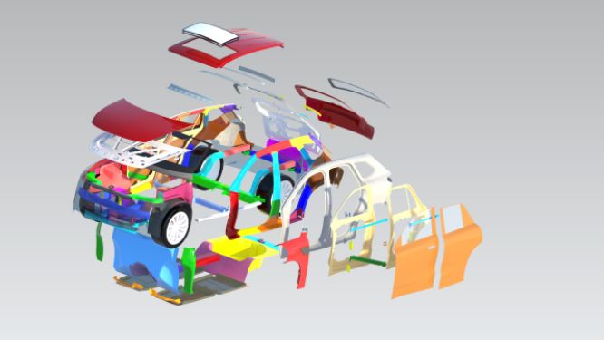
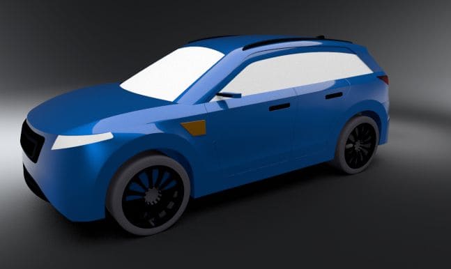
Roof Design
AUTOMOTIVE SHEETMETAL ROOF DESIGN USING NX CAD Objective Designing of Front roof rail, rear roof rail, bow roof front, bow roof rear, center roof rail and Reinforcement are creating to build the strong roof. To Perform a curvature study on the roof and perform the calculations for the heat distortion and…
Jishnu Haridas
updated on 29 Apr 2023


AUTOMOTIVE SHEETMETAL ROOF DESIGN USING NX CAD
Objective
- Designing of Front roof rail, rear roof rail, bow roof front, bow roof rear, center roof rail and Reinforcement are creating to build the strong roof.
- To Perform a curvature study on the roof and perform the calculations for the heat distortion and snow load criteria to determine whether the bow roofs are at the correct positions.
- Curvature study on Roof and performance calculations for Heat distortion and Snow load criteria to determine the position of the Bow roofs.
- Finding moment of inertia and section modulus for Bow roofs , central roof rail . front roof rail and rear roof rail .
- Draft analysis
Design Considerations
- Visibility criteria
- Head room clearance
- Bow roof position
- Heat distortion and Snow load criteria
- Draft analysis
Reinforcements
- Front roof rail
Joins the wind shield glass ,body side outer and the inner panel.
- Bow roof and Center Roof Rail

Bow roofs are give to improve the torsional stiffness and load bearing capacity of the roof structure . The number of bow roof present is depends on the overall size of the roof .
Central roof rail is placed at the center of the roof which is connected to the B-pillar support structure . This central roof rail helps in adding the strength to the roof during the rool- over test.
- Back Roof Rail

Joins the back door and the body side outer
ROOF CRUSH TEST :
After analyzing the many accidents IIHS has then fixed some regulations which needs to consider by the design engineers given by the IIHS (Insurance Institute of Highway Safety)
IIHS gives the rating based up on this test . For this they consider two points while giving the rating
- How fast the car can reforms to its original shape after the roll over and
- How deep is the protrusion after the roll over

The load is applied in such a way that 50 is tilted from the front end to the rear end and the load will be in 1800 mm in length and 750 mm in width . The load is applied at the position of 250 from the flatness of the roof . The load is applied on the roof for almost 120 sec and the crush speed at which the load applied is 13 mm/sec or less than that


The analysis is carried out with defined boundary conditions. The results are compared between baseline and modified
Model.

If the displacements goes above the requirements level then we have to increase the bow roof thickness or add more mastics points to increase the strength . the stronger the roof the better it can protect the occupants in the roll over crashes.
Draft Analysis
The Draft Analysis enables you to detect if the part you drafted will be easily removed. This type of analysis is performed based on color ranges identifying zones on the analyzed element where the deviation from the draft direction at any point, corresponds to specified values.
Draft angle =7 degree
Green colour show positive draft angle of the part more than 7 degree.
Given below is the draft analysis of each parts in the Roof Assembly:


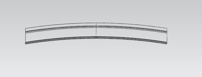
THE CURVATURE STUDIES ON THE ROOF :
- HEAT DISTORTION STUDY ON THE ROOF
- SNOW LOAD CRITERIA
The Heat Distortion study plays a major role in sheet metal usage . heat distortion temperature is a temperature limit above which the material cannot be used for the structural applications . This study is used to predict the heat distortion temperature at where the material starts to soften when exposed to a fixed load at elevated temperature . In order to avoid bending or damages on the roof, based on the heat distortion temperature , this study will predict the bow roof position which helps to strengthen the roof .
Bow – roof prediction Formula
W = [1.73 x 10^(-3) x L] + [1.85 x 10^(-8) x (R^2)/t] + [ 1.10x10^(-3) x l] - 2.68
Where
L = Roof Length in X-Direction[mm](Roof dimension in 0-Y)
R = Roof curvature
R = 2(Rx*Ry)/(Rx+Ry)
Rx = X curvature
Ry = Y curvature
t = Roof plate thickness [mm]
l = Bow Roof Span [mm]
Judgment Condition
OK< 2.7


| Roof Rail | Rx (mm) | Ry (mm) | Rx+Ry | Rx*Ry | R (mm) | L (mm) | t (mm) | l (mm) | W (mm) | Result |
| Front Roof- Bow | 5764 | 2888 | 8652 | 16646432 | 3847.9 | 2075.5 | 0.75 | 501.07 | 1.82 | Pass |
| Bow- Center Bow | 4714 | 7344 | 12058 | 34619616 | 5742.1 | 2075.5 | 0.75 | 479.7 | 2.25 | Pass |
| Centerbow- Back Roof | 3484 | 13339 | 16793 | 46072906 | 5487.15 | 2075.5 | 0.75 | 673.7 | 5.07 | Fail |
From the above table it can be concluded that all values of W is not <2.7
So thus infers that current positioning of bow row is not in good state as per design
SNOW LOAD CRITERIA :
This test is done to know how is the roof behaving when there is a snow over . normally due to the snow weight the dent will happen. But the roof should be designed in such a way that when the snow is removal the roof should go it its original position . This is the basic requirements for snow load criteria .
Qr = [Iy x t2] / [α x s x [(Rx + Ry)/2]2 x 10-8]
Where
α = My x Lx2 x 10-12 , My = Y(Ly-Y)
Judgement condition = Qr ≥ 3.1
250 ≤ s ≤ 380
t = Roof plate thickness [mm]
Ly = Distance between the front and rear roof Rails on the Vehicle along with 0Y[mm]
Length of Roof panel with the center point between Roof rail Front /Rear as the reference point of the front and the rear.
Lx = Distance between the Left and Right end of the roof on the Roof BOW [mm]
Width of the roof panel exposed on the surface.
Y = Distance front Front Roof Rail to Roof BOW[mm]
s = Distance for which Roof BOW bears divided load [mm]
s = L1/2 + L2/2
Iy = Geometrical moment of inertia of Roof BOW (Y cross-section )[mm4]
Rx = Lateral direction curvature radius of roof panel Y cross-section on Roof BOW [mm]
Roof panel curvature Radius of the Length Lx in Front view
Ry = Longitudinal Direction curvature radius of the Roof panel X cross-section on Roof BOW [mm]
Judgement condition = Qr > 3.1


 LX
LX
 LY
LY
 Y
Y
 L1 L2 CASE1
 L1 L2 CASE2
 L1 CASE3
Section analysis
 Center Roof Rail
Moment of inertia maximum,( MAX) I max =1.423×10⁴ ( mm4)
Moment of inertia minimum ,( MIN) I min =538.442 ( mm4)
We take the Minimum moment of inertia value is IY1 = 538.442mm4.
 Bow Roof
Moment of inertia maximum,( MAX) I max =3.187×10³ ( mm4)
Moment of inertia maximum ,( MIN) I min =333.057 ( mm4)
We take the Minimum moment of inertia value is IY1 = 333.057mm4.
 Back Rail
Moment of inertia maximum,( MAX) I max =2.025×10^4 ( mm4)
Moment of inertia maximum ,( MIN) I min =1.106×10^3 ( mm4)
We take the Minimum moment of inertia value is IY1 = 1106.5 mm4.
| Roof Rails | ly (mm) | Lx | Ly | L1 | L2 | Rx | Ry | t | Y | S | My | α | ((Rx+Ry)/2 ^2 | Qr | Result |
| Front Roof- Bow | 538.442 | 1054.9 | 2118.9 | 619.7 | 528.4 | 4413.32 | 2775.91 | .75 | 904.6 | 574.05 | 1098455.78 | 1.22 | 1292125 | 3.34 | PASS |
| Bow- Center Bow | 333.057 | 1084.8 | 2118.9 | 528.4 | 574.3 | 3872.04 | 7429.15 | .75 | 1479 | 551.35 | 946412.1 | 1.11 | 31929223.85 | 16.54 | PASS |
| Centerbow- Back Roof | 1106.5 | 1137.5 | 2118.9 | 574.3 | 904.6 | 4284.59 | 14262.07 | .75 | 2118.9 | 739.45 | 2922916.605 | 3.78 | 85994649.29 | 7.12 | PASS |
Judgement condition = Qr > 3.1 in all cases
So thus infers that current positioning of bow row is in good state as per design.
SECTION MODULUS:
The moment carrying capacity of an object is directly dependent on geometrical property (I) and material property (E) of an object, which is collectively termed as flexural rigidity (EI). Geometry of an object plays an important role in load bearing capacity of an object which is indicated by moment of inertia of a section.
Therefore, section modulus is the predominant factor which evidences the strength of an object and is defined as the ratio of the moment of inertia of the object about its centroidal axis to the distance of the extreme fibers of the object from the neutral axis.
There are two types of section modulus we have,
- Elastic section modulus
- Plastic section modulus
Elastic modulus is defined as,
S = I/Y
S – Section modulus,
I – Second moment of area
Y – distance from the neutral axis to outer most fiber of the object.
 BOW ROOF RAIL
Moment of inertia (Max), Imax = 3.187 x 10^3 mm4
Moment of inertia (Min), Imin = 333.05 mm4
Section modulus = moment of inertia / distance between the neutral axis to extreme end of the object.
S = I/Y
Y = 22.5 mm
For maximum MOI,
S = 3.187 x 10^3/22.5
SMAX = 141.64 mm3
For minimum MOI,
S = 333.05/22.5
SMIN = 14.8 mm3
 CENTER ROOF RAIL
Moment of inertia (Max), Imax = 1.423 x 10^3 mm4
Moment of inertia (Min), Imin = 538.442 mm4
Section modulus = moment of inertia / distance between the neutral axis to extreme end of the object.
S = I/Y
Y = 16.5 mm
For maximum MOI,
S = 1.423 x 10^3/16.5
SMAX = 86.24 mm3
For minimum MOI,
S = 538.442/45
SMIN = 11.96mm3
BACK RAIL
Moment of inertia (Max), Imax = 2.025 x 10^4 mm4
Moment of inertia (Min), Imin = 1.106 x 103 mm4
Section modulus = moment of inertia / distance between the neutral axis to extreme end of the object.
S = I/Y
Y = 31.3 mm
For maximum MOI,
S = 2.025 x 10^4/31.3
SMAX = 646.96 mm3
For minimum MOI,
S = 1.106 x 10³/31.3
SMIN = 35.33 mm3
 FRONT RAIL
Moment of inertia (Max), Imax = 1.19 x 10^4 mm4
Moment of inertia (Min), Imin = 430.55 mm4
Section modulus = moment of inertia / distance between the neutral axis to extreme end of the object.
S = I/Y
Y = 32 mm
For maximum MOI,
S = 1.19 x 10^4/32
SMAX = 371.87 mm3
For minimum MOI,
S = 430.55/32
SMIN = 13.45 mm3
CONCLUSION :
- The Roof , Front Roofrail, Back Roofrail, Bow Roofrail and Central roof rail is designed by following the master sections.
- The Curvature studies of the Roof is Carried out.
- The moment of inertia and draft analysis are carried out to check feasibility manufacturing.
Leave a comment
Thanks for choosing to leave a comment. Please keep in mind that all the comments are moderated as per our comment policy, and your email will not be published for privacy reasons. Please leave a personal & meaningful conversation.
Other comments...
Be the first to add a comment
Read more Projects by Jishnu Haridas (19)
Design of backdoor
DESIGN OF BACKDOOR USING NX-CAD OBJECTIVES Using the provided styling surface Appropriate design methodologies Make the necessary reinforcements Embosses Backdoor design is formulated. While coming to the design and functionality of the backdoor, ensuring that it aligns with the overall aesthetic…

31 May 2023 08:02 AM IST
Roof Design
AUTOMOTIVE SHEETMETAL ROOF DESIGN USING NX CAD Objective Designing of Front roof rail, rear roof rail, bow roof front, bow roof rear, center roof rail and Reinforcement are creating to build the strong roof. To Perform a curvature study on the roof and perform the calculations for the heat distortion and…
29 Apr 2023 09:24 AM IST
Fender Design
Designing Of Fender (NX-CAD) Car fenders play an important role in protecting the vehicle from debris and also contribute to the overall aesthetics of the vehicle. The materials used for fenders include steel, aluminum, and plastic, each with its own unique properties. The manufacturing process for fenders varies…
30 Mar 2023 10:39 AM IST
Fender Design - Wheel Arch Challenge
Fenger Design - Wheel Arch Calculation Aim : To Decide weather the given design passes the European Regulations Requirement The Given Design of Fender wheel arch : European Regulations Requirement: The Sketch which is made according to the European Standards According to the European…
25 Mar 2023 01:18 PM IST
Related Courses


Skill-Lync offers industry relevant advanced engineering courses for engineering students by partnering with industry experts.


Our Company

4th Floor, BLOCK-B, Velachery - Tambaram Main Rd, Ram Nagar South, Madipakkam, Chennai, Tamil Nadu 600042.

Top Individual Courses
Top PG Programs
Skill-Lync Plus
Trending Blogs
© 2025 Skill-Lync Inc. All Rights Reserved.