


Courses by Software
Courses by Semester
Courses by Domain
Tool-focused Courses
Machine learning
POPULAR COURSES
Success Stories

Week 8 - Challenge 2 - Switch Bezel Design
AIM Create the swutch bezel plastic component through the given class A surface. To begin with,the tooling axis for the given class A surface should be created meeting the requirements of the draft angle and at the end perform the draft analysis on the model OBJECTIVE The objective of the project is to design the switch…
Naresh Kumar
updated on 08 Nov 2022


AIM
Create the swutch bezel plastic component through the given class A surface. To begin with,the tooling axis for the given class A surface should be created meeting the requirements of the draft angle and at the end perform the draft analysis on the model
OBJECTIVE
The objective of the project is to design the switch bezel and to do a draft analysis for it by creating the required tooling direction with the help of Bisecting method.
INTRODUCTION
The control panel bezel is the frame part of the window switch that holds its switch covers and buttons into place. Moulding is the method used to manufacture the plastic trims of an automotive by most OEM’s, hence by considering the manufacturing consideration the switch bezel is designed.
DESIGN CONSIDERATION
- Class – A surface should be aesthetically smooth and good.
- Class – B surface should have all the supporting features like ribs.
- Parting Line should coincide with the B surface since flashing couldn’t affect the aesthetic of Class – A.
- Class – C surface should also pass the draft analysis.
MATERIAL USED:
- Acrylonitrile butadiene styrene (ABS)
- NYLON 6/6.its unreinforced stste , it is an extremely rigid , abrasion-resistant,heat-resistantand hard material
PROCEDURE FOR CREATING THE SWITCH BEZEL
- First, the given styling surface is checked for any irregularities and if found any then it is corrected by using Trim, Extrapolate, Split and Join commands.
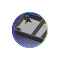
- The below image shows that the Class – A surface is clean and no irregularities present, so let's move on to the next step.
CLASS-A SURFACE: the class-A surface is used in the automotive design industry. it describes the final production surface data for the aesthetic parts.

CREATING TOOLING AXIS:
- Considering the Ejection from the cavity of the mould after manufacturing the interior trim (switch bezel) must have the nominal 3-degree draft angle.
- Hence the tooling direction is created by considering the above factor and bisecting method is used.
- The base surface of the class – A was extracted and a point at the centre is created and an axis system was inserted to the point with the current feature is disabled.
- Then, using project intersection along yz plane is created and the two inclined lines were drawn inside the positioned sketch.
- Then bisecting lines with the two inclined lines were drawn.
- Now the same procedure is done along the xz plane but on one side we don’t have inclined lines so the centre point is used to extrude a line along the z-direction and gave a measurement of 5 degrees (Tentatively).
- With these two lines from sketches 1 and 2, the bisecting line is crated and published as Tooling Axis(tooling direction).

CREATION OF CLASS B SURFACE
The class-B surface is the second surface that has a certain thickness from the class-A surface. this surface contains engineering aspects of a model. These must be smooth and "error-free" as well but are not held to the standards that class A surfaces
- For creating the class-B surface the required surface except the offset surface have been extracted and then untrimmed all the surface.
- Then all the surfaces have been extrapolated to get intersections between them.
- Since the thickness of the Switch bezel is 2.5mm the B-Surface was offset to 2.5 mm and the required trim operations must be carried out.
- Finally, the required corners have been filleted to 12.5mm (15mm-2.5mm). [ 15mm - fillet value of the A-surface, 2.5mm – Thickness of the component ]

CREATION OF CLASS C SURFACE
The Class C finish allows more imperfections than Class A or B. Class C is often specified for interior surfaces not readily visible, surfaces that will be covered by another part when assembled, or surfaces
- The required outer edges of the A-Surface were extracted using Multiple Extract. Then for avoiding the patches the curve is smoothened using the Curve Smooth option.
- Then by using the sweep command the surface was created with the following feature controls,
- Profile type – Line
- Subtype – With Draft Direction
- Guide Curve – Smooth Curve
- Draft Direction – Tooling Axis
- Draft Computation Mode – Square
- Length – 20mm
- Then by using extrapolate command the edges were intersected between the surface corners which eases the trimming operation.
- Now the required portion of the C – surface were trimmed out.

CREATION OF CLOSED SURFACE
- Now the class – A and Class- C surfaces were joined together by removing the gaps in-between them with the help of extrapolation(tangent continuity) and Trim surface.
- Then the exact surface of the Switch bezel was trimmed from the above-resulted trim surface with the class-B surface.
- Then, by defining the part body by using the Closed Surface command in Part Design, the component's solid body is created.

DRAFT ANALYSIS FOR CLASS A
- Go to insert> analysis> feature draft analysis
- Align the tooling axis with the compass.
- Click on the surface and see that the surface is within the permissible limit of the draft values.
- The surface should be green and in the column nominal value 2.9deg given as input. hence the draft analysis on the class-A surface is successfully performed.

DRAFT ANALYSIS FOR OVERALL

PROCEDURE FOR DRAFT ANALYSIS
- First the class – A surface is checked before creating the Class –B&C surface and finally the solid body must be analysed. Both can be done by following the below procedures.
- By changing the view mode to custom view parameters – Material mode then the feature draft analysis is enabled.
- Then the compass was activated and placed with the tooling axis by dragging the red pointer and then locked it.
- Then, by selecting the quick analysis mode, the nominal value will be 3 degrees and checked for the component's draft angle.
- The green colour area shows that it satisfies the 3-degree draft angle. If not satisfied then by using the Running point tool the area is measured and then altered to get a successful draft for the created tooling direction.
FINAL RESULT

CONCLUSION
Finally the Class – A, B&C surfaces with the Tooling Direction have been Published and the Switch Bezel is moved on to the designing of the next operation – the creation of B-side features.

Leave a comment
Thanks for choosing to leave a comment. Please keep in mind that all the comments are moderated as per our comment policy, and your email will not be published for privacy reasons. Please leave a personal & meaningful conversation.
Other comments...
Be the first to add a comment
Read more Projects by Naresh Kumar (29)
Week 4 Challenge
Operation to do: Joining of Class A surface. Create Tooling Axis. Create Draft Analysis for Class A Surface. Create Class B Surface. Create Class C Surface. Create Final Product. Material used in Lens: Poly Carbonate. Followed Constrains: The change in dimension of the Class A Surafce is not allowed. Change in thickness…

29 Mar 2023 06:21 AM IST
Week 3 Challenge
Operation to do: Joining of Class A surface. Create Tooling Axis. Create Draft Analysis for Class A Surface. Create Class B Surface. Create Class C Surface. Create Final Product. Material used in Lens: Poly Carbonate. Followed Constrains: The change in dimension of the Class A Surafce is not allowed. Change in thickness…
29 Mar 2023 06:03 AM IST
Project 2
Objective: Route the Wiring harness on Given car body and Prepare flatten view drawing in CATIA V5. Application of all Packaging rules, Industry best practices studied in this course shall be demonstrated in design. Apply Protection coverings as required. Back Door Assembly Part: Construction of the Harness Assembly Bundle:…
28 Feb 2023 06:34 AM IST
Project 1
AIM: To route the wiring harness on given Engine and flatten view drawing in CATIA V5. Route the Wiring harness on Given Engine and Prepare flatten view drawing in CATIA V5. Application of all Packaging rules, Industry best practices studied in this course shall be demonstrated in design. Apply Protection coverings as…
21 Feb 2023 10:11 AM IST
Related Courses


Skill-Lync offers industry relevant advanced engineering courses for engineering students by partnering with industry experts.


Our Company

4th Floor, BLOCK-B, Velachery - Tambaram Main Rd, Ram Nagar South, Madipakkam, Chennai, Tamil Nadu 600042.

Top Individual Courses
Top PG Programs
Skill-Lync Plus
Trending Blogs
© 2025 Skill-Lync Inc. All Rights Reserved.