


Courses by Software
Courses by Semester
Courses by Domain
Tool-focused Courses
Machine learning
POPULAR COURSES
Success Stories

Week 1:- Introduction to BiW and Fixtures Challenge
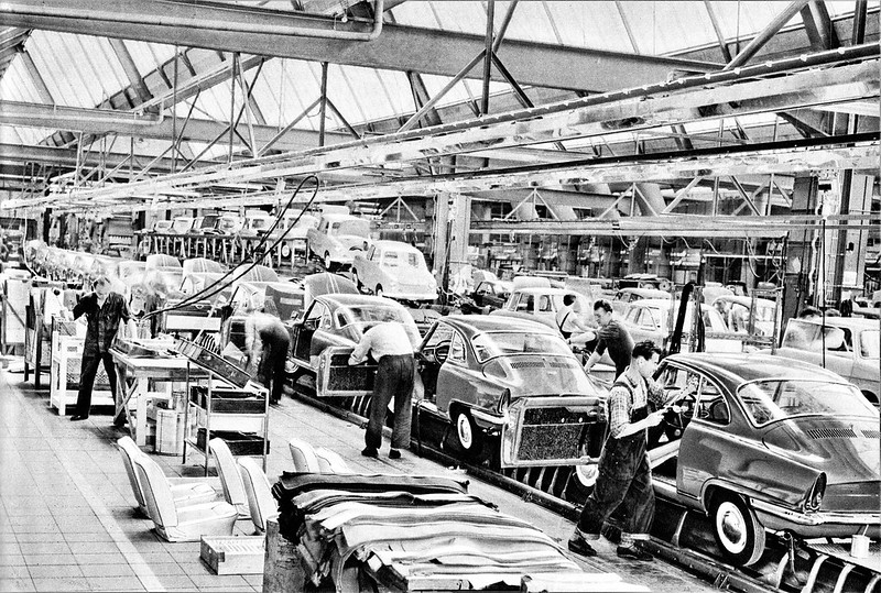
1.Body in white (BIW) is the stage in automobile manufacturing in which a car body's frame has been joined together, that is before painting and before the motor, chassis sub-assemblies, or trim (glass, door locks/handles, seats, upholstery, electronics, etc.) have been integrated into the structure. Assembly involves…
Janardhan Gonthina
updated on 15 May 2023


1.Body in white (BIW) is the stage in automobile manufacturing in which a car body's frame has been joined together, that is before painting and before the motor, chassis sub-assemblies, or trim (glass, door locks/handles, seats, upholstery, electronics, etc.) have been integrated into the structure. Assembly involves different techniques such as welding (spot, MIG/MAG, or friction stir), riveting, clinching, bonding and laser brazing.
_hatchback,_body_in_white_(2010-10-16)_04.jpg)
-
Underbody structure.
-
Front end structure.
-
Body side structure.
-
Closure.
-
Roof.
2.
BiW nomenclature is the different names given to different components in sheet metal structure of body.
BiW or Body in White is basically spread into various different parts and components and to define them BiW nomenclature is used.
Through nomenclature, we give different names to different parts so that it becomes easier to define them.
A nomenclature in BIW is basically naming every part of the body. These names can be said as subparts of the already categorized parts above. The nomenclature differs a little bit from region to region but the overall idea is to name individual automotive sheet metal components. Below images show the nomenclature of BIW:

3.
Though the two terms are used interchangeably, jigs and fixtures are actually very different devices that are mostly used in conjunction with one another. These devices are mostly used in machining operations to help reduce human effort during mass production.
However, in this guide, we’ll focus primarily on different types of fixtures, their purpose, advantages, and what industry relies on them the most.
The Most Common Types of Fixtures Used in Manufacturing
Fixtures are specifically designed for applications where the cutting tool can’t be easily guided via different types of jigs. Since they’re used in almost any machining operation based on the precise relationship between the workpiece and the cutting tool, these devices are often identified by the machining tools they’re used on. Below, we differentiate the following types based on fixture design:
Turning Fixtures
They are usually mounted on chucks of the machine spindle during turning operations, like on lathes. Depending on the part that’s being machined, turning fixtures may be equipped with counterweights to balance an unbalanced fixture.
Milling Fixtures
Milling fixtures are usually mounted on machining tables facing the faceplate or the spindle of the milling machine. The workpiece is placed at the base of the fixture and clamped before starting milling operations. However, during operation the cutting tool remains in place while the machining table, alongside the piece, shifts in relation to the cutter.
Boring Fixtures
Boring fixtures incorporate the principles of drill jigs since the boring bar is guided through a pilot bushing, similar to drill bushing. Its main function is to hold the workpiece in the correct position relative to the boring bar. Since they aren’t subject to strong cutting forces, boring fixtures don’t need to be as sturdy.
Grinding Fixtures
There are several different forms of grinding fixtures used in grinding machines to hold, locate, or support workpieces that are subject to grinding operations. Regardless of their form, however, these should have provisions for the supply and exit of coolant.
Tapping Fixtures
These work holding devices are specifically designed to position and secure workpieces for tapping operations — cutting internal threads in drill holes. They’re primarily used on odd-shaped and imbalanced parts, especially in mass production, for drilling, tapping, and reaming.
Indexing Fixtures
These are specifically used for machining parts that must have machined details evenly spaced.
Welding Fixtures
Welding fixtures are designed to hold and support different components intended for welding operations and to prevent any possible distortions in welded structures. The structure of these fixtures has to be rigid and stable, and the clamping elements need to be positioned clear of the welding area.
Duplex Fixtures
Duplex fixtures are designed to facilitate simultaneous machining of two parts at separate machining stations. Depending on the manufacturing needs, these parts can be machined identically or in sequence.
Assembly Fixtures
These are used to hold various parts and components together for assembly purposes. They’re similar to welding fixtures, but instead of hot joining, these are used for mechanical assembly.
Broaching Fixtures
Mostly used with plate fixtures, broaching fixtures are used to hold the workpiece during broaching operations.
4.Design principles of Jigs and Fixtures
The art of metalworking has a primary concern, locating the part to be machined relative to the platform. A CNC machine starts machining at a specific point corresponding to the fixture and proceeds from there. Therefore, the preciseness with which a job is machined is dependent on the accuracy that holds in the fixture. The accurate location of every part loaded into the fixture is essential. Any deviation in part location adds to the dimensional tolerance that must be assigned to the finished pieces. Furthermore, improper supporting and securing the part in the fixture affects surface finishes by temporarily or permanently deforming it. Hence, techniques for supporting, clamping, and locating must be considered together to assure repeatability from part to part.
Basic principles of Jigs and Fixtures design
LOCATING POINTS: Locating the work is a prime necessity and requires suitable facilities. The correct setup ensures smooth insertion of a workpiece in the proper position and removing a workpiece from a jig without operational hassles or time consumption. The workpiece position needs to be precise with the guiding tool in the jig or setup pieces in the fixture.
FOOLPROOF: A foolproof design of jigs and fixtures does not permit a tool or workpiece to be placed in any other way other than the intended one.
REDUCTION OF IDLE TIME: Jigs and Fixtures must be designed in such a way that ensures smooth loading, clamping, machining, and unloading of a
WEIGHT OF JIGS AND FIXTURES: A jig and fixture must be compact, easy to handle, and low cost regarding the number of materials used without giving up stiffness and rigidity.
JIGS PROVIDED WITH FEET: Some jigs require feet so that they can be placed on the table firmly.
MATERIALS FOR JIGS AND FIXTURES: Jigs and Fixtures are usually created with hardened materials to resist wear & tear and avoid frequent damage—for example, Mild steel, Cast iron, Die steel, High-speed steel, Caesium.
CLAMPING DEVICE: A suitable clamp is rated for its strength. It should be able to hold a workpiece firmly in its position while bearing the strain of the cutting tool simultaneously, without springing.
5.In BIW fixture designing we have various stations which are used to locate the panels so that joining processes can be done.
Leave a comment
Thanks for choosing to leave a comment. Please keep in mind that all the comments are moderated as per our comment policy, and your email will not be published for privacy reasons. Please leave a personal & meaningful conversation.
Other comments...
Be the first to add a comment
Read more Projects by Janardhan Gonthina (28)
Week 1:- Introduction to BiW and Fixtures Challenge
1.Body in white (BIW) is the stage in automobile manufacturing in which a car body's frame has been joined together, that is before painting and before the motor, chassis sub-assemblies, or trim (glass, door locks/handles, seats, upholstery, electronics, etc.) have been integrated into the structure. Assembly involves…

15 May 2023 04:12 PM IST
Project 2
AIM Route the Wiring harness on Given car body and Prepare flatten view drawing in CATIA V5. Application of all Packaging rules, Industry best practices studied in this course shall be demonstrated in design. Apply Protection coverings as required. Given car back door cad data …
08 May 2023 03:49 PM IST
Project 1
AIM Route the Wiring harness on Given Engine and Prepare flatten view drawing in CATIA V5. Application of all Packaging rules, Industry best practices studied in this course shall be demonstrated in design. Apply Protection coverings as required. ENGINE WIRING HARNESS ROUTING …
07 May 2023 06:10 AM IST
Wiring harness design in CATIA V5 - 3D modeling Week 7 Challenge
AIM: TO FLATTEN THE WIRING HARNESS AND DRAFT THE WIRING HARNESS ASSEMBLY. GIVEN: HARNESS ASSEMBLY: HARNESS FLATTENING: WE GO TO THE HARNESS FLATTENING WORKBENCH AND DEFINE THE FLATTENING PARAMETERS. WE USE THE EXTRACT COMMAND TO BRING THE HARNESS ASSEMBLY TO THE FLATTENING WORKBENCH HERE. CHOOSING A SUITABLE PLANE WE FLATTEN…
01 May 2023 04:35 AM IST
Related Courses


0 Hours of Content
Skill-Lync offers industry relevant advanced engineering courses for engineering students by partnering with industry experts.


Our Company

4th Floor, BLOCK-B, Velachery - Tambaram Main Rd, Ram Nagar South, Madipakkam, Chennai, Tamil Nadu 600042.

Top Individual Courses
Top PG Programs
Skill-Lync Plus
Trending Blogs
© 2025 Skill-Lync Inc. All Rights Reserved.