


Courses by Software
Courses by Semester
Courses by Domain
Tool-focused Courses
Machine learning
POPULAR COURSES
Success Stories

Project 2 Adaptive Cruise Control
Aim: To create a Simulink Data Dictionary, develop an algorithm for Adaptive Cruise Control and generate a C code for it using Simulink. Objective: 1. Developing Adaptive Cruise Control feature as per the Requirement Document using MATLAB Simulink. 2. Follow all the MBD-related processes: Requirement…
Parvez Khan
updated on 16 Oct 2021


Aim: To create a Simulink Data Dictionary, develop an algorithm for Adaptive Cruise Control and generate a C code for it using Simulink.
Objective:
1. Developing Adaptive Cruise Control feature as per the Requirement Document using MATLAB Simulink.
2. Follow all the MBD-related processes: Requirement Tagging & Traceability, SLDD creation, Configuration Parameter changes, Model Advisor check & Code Generation.
Overview:

Adaptive Cruise Control Feature for passenger cars allows the host vehicle to adapt to the speed in line with the flow of traffic. Driving in heavy traffic or keeping a safe distance to the preceding vehicle calls for a high level of concentration. The Adaptive Cruise Control feature can reduce the stress on the driver by automatically controlling the vehicle speed & maintaining a predefined minimum distance to the preceding vehicle. As a consequence, the driver enjoys more comfort & can concentrate on the road a little better.
A radar sensor is usually at the core of the Adaptive Cruise Control. Installed at the front of the vehicle, the system permanently monitors the road ahead. As long as the road ahead is clear, the cruise control feature maintains the speed set by the driver. If the system spots a slower vehicle within its detection range, it gently reduces speed by releasing the accelerator or actively engaging the brake control system. If the vehicle ahead speeds up or changes lanes, the cruise control automatically accelerates to the driver’s desired speed.
Standard Adaptive Cruise Control can be activated from speeds of around 30 km/h (20 mph) upwards and supports the driver, primarily on cross-country journeys or on freeways. The cruise control stops & go variant is also active at speeds below 30 km/h (20 mph). It can maintain the set distance to the preceding vehicle even at very low speeds and can decelerate to a complete standstill. When the vehicle remains stopped longer, the driver needs only to reactivate the system, for example by briefly stepping on the gas pedal to return to cruise control mode. In this way, cruise control stops & goes supports the driver even in heavy traffic and traffic jams.
Since Adaptive Cruise Control is a comfort and convenience system, brake interventions and vehicle acceleration only take place within defined limits. Even with Adaptive Cruise Control switched on, it remains the driver’s responsibility to monitor the speed and distance from the vehicle in front.

Adaptive cruise control typically uses radar in a frequency band that doesn’t compete with police radar and doesn’t trigger radar detectors. For full-range ACC, some automakers use two radars — one for close range out to about 100 feet and a second that sees out to about 600 feet, or about 6-7 seconds at highway speeds. Partial ACC is usually a single unit, while some full-range ACC implementations can now use a single radar.
Early ACC units were a competing mix of laser on some cars and radar on the others. Radar won out because it works better in bad weather and costs came down to be competitive with a laser. Even so, some ACC is optical. Subaru uses two cameras flanking the rearview mirror for its EyeSight system. It also provides unassisted automatic braking at low speeds if a pedestrian or stopped car gets in your path.
The effectiveness of even radar-based ACC is compromised in bad weather. It will shut off in heavy rain or snow (you get a warning) or if the sensor in the grille or under the bumper is caked with snow or dirt. So far, adaptive cruise control doesn’t adjust to changing speed limits. The technology exists to do that: speed limit info is in navigation system map data, and lane departure warning cameras have the ability to read speed limit signs. In theory, you could tell ACC that you want your top speed at highway speeds to be the posted limit plus 5 mph. Then when you hit a construction zone posted for 45 mph, you’ll stay reasonably close to the limit.
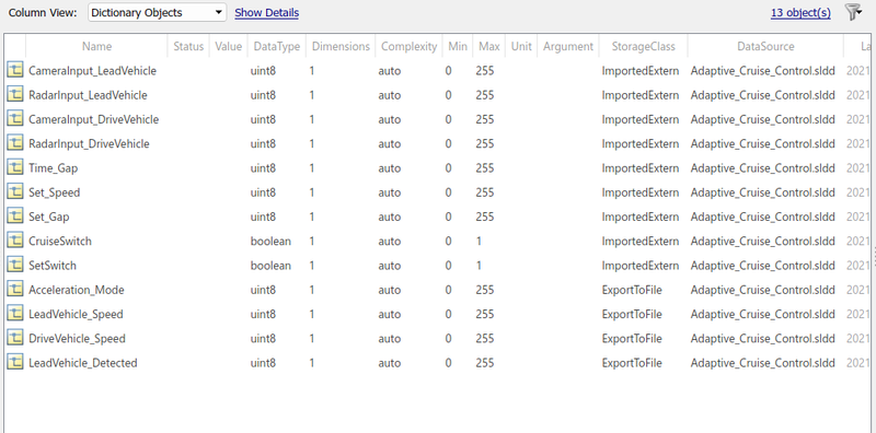
Signals & Calibration Data list:
|
Signal / Calibration Name |
Signal Type |
Data Type |
Dimension |
Min |
Max |
Initial Value |
Units |
|
CameraInput_LeadVehicle |
Input |
Uint8 |
1 |
0 |
255 |
- |
- |
|
RadarInput_LeadVehicle |
Input |
Uint8 |
1 |
0 |
255 |
- |
- |
|
CameraInput_DriveVehicle |
Input |
Uint8 |
1 |
0 |
255 |
- |
- |
|
RadarInput_DriveVehicle |
Input |
Uint8 |
1 |
0 |
255 |
- |
- |
|
Time_Gap |
Input |
Uint8 |
1 |
0 |
255 |
- |
- |
|
Set_Speed |
Input |
Uint8 |
1 |
0 |
255 |
- |
- |
|
Set_Gap |
Input |
Uint8 |
1 |
0 |
255 |
- |
- |
|
CruiseSwitch |
Input |
Boolean |
1 |
0 |
1 |
- |
- |
|
SetSwitch |
Input |
Boolean |
1 |
0 |
1 |
- |
- |
|
Acceleration_Mode |
Output |
Uint8 |
1 |
0 |
255 |
- |
- |
|
LeadVehicle_Speed |
Output |
Uint8 |
1 |
0 |
255 |
- |
- |
|
DriveVehicle_Speed |
Output |
Uint8 |
1 |
0 |
255 |
- |
- |
|
LeadVehicle_Detected |
Output |
Uint8 |
1 |
0 |
255 |
- |
- |
Procedure:
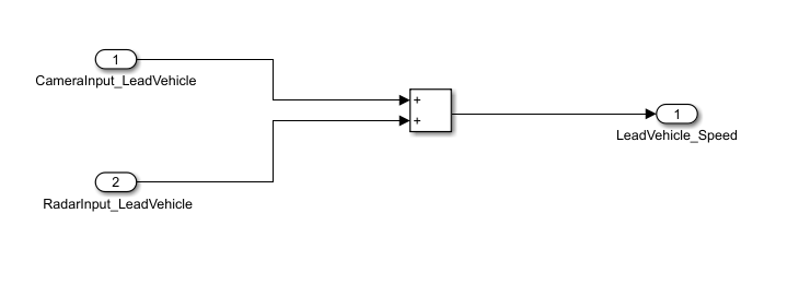
Requirement 1– Lead Vehicle:
- A lead vehicle is a vehicle that is driving in the road ahead of our drive vehicle. Two input signals (Signal Name: CameraInput_LeadVehicle & RadarInput_LeadVehicle).
- Ideally, sensor fusion techniques will be deployed to process & analyze data from cameras & radar. For complexity reasons, let’s not adapt to any such algorithms.
- We can simply add both the radar & camera inputs & the corresponding output is read as Speed profile output (Signal Name: LeadVehicle_Speed).
- Speed data of the lead vehicle is critical in implementing the Adaptive Cruise Control algorithm.
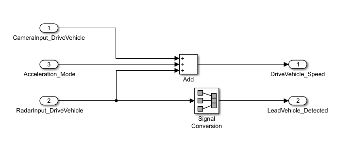
Requirement 2 – Drive Vehicle:
- Drive Vehicle is the vehicle driven by the user & this is the vehicle that has ACC algorithm in it.
- Like the Lead Vehicle, the Driver Vehicle algorithm also has 2 input signals (Signal Name: CameraInput_DriveVehicle, RadarInput_DriveVehicle) & one signal coming as an Input to this subsystem (Signal Name: Acceleration_Mode) – three inputs into this requirement in total.
- Like the above requirement, sensor fusion techniques will also be deployed here, for complexity reasons we are ignoring them.
- Two output signals come from this subsystem (Signal Name: DriveVehicle_Speed & LeadVehicle_Detected).
- Signal DriveVehicle_Speed is the summation of three input signals mentioned above & LeadVehicle_Detected is renamed from Input Signal RadarInput_DriveVehicle by mere use of Signal Conversion block.
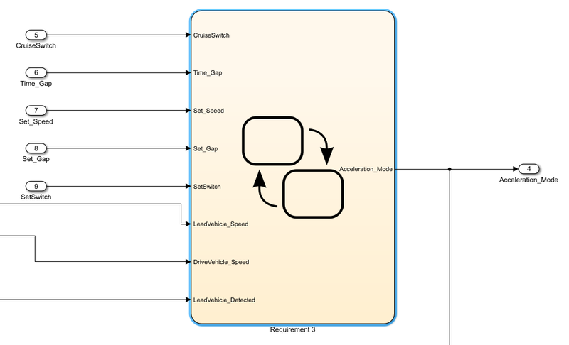
Requirement 3 – Adaptive Cruise Control Algorithm:
- Adaptive Cruise Control feature has 3 major modes of operation: OFF Mode, STANDBY Mode & ON Mode. This particular requirement has to be implemented as state machine logic in Simulink.
- The input signals to this state machine system are (Signal Name: Time_Gap, Set_Speed, Set_Gap, CruiseSwitch, SetSwitch).
- Also, the output signals (Signal Name: DriveVehicle_Speed & LeadVehicle_Detected) from requirement-2 are fed back as an input signal into this state machine block.
- Additionally, the output signal (Signal Name: LeadVehicle_Speed) from requirement-1 is given as an input signal to this state machine block as well.
- The output from this subsystem is a signal (Signal Name: Acceleration_Mode) which governs the vehicular speed of the drive vehicle which automatically adjusts its speed & velocity to match the lead vehicle.
Requirement 3a – ACC OFF MODE state logic:
- This is the default state inside state machine logic. Output signal Acceleration_Mode is at value 0 in this state.
- This state is governed by the input signal CruiseSwitch.
- If CruiseSwitch is equal to 1, state ACC STANDBY mode will get activated. If CruiseSwitch is equal to 0, state ACC OFF mode will get activated, from either ACC ON mode or ACC STANDBY mode
Requirement 3b – ACC STANDBY MODE state logic:
- This is the second activated state inside state machine logic. Output signal Acceleration_Mode is at value 1 in this state.
- This state is governed by both input signals CruiseSwitch & SetSwitch.
- If CruiseSwitch is equal to 1, state ACC STANDBY mode will get activated. If CruiseSwitch is equal to 0, state ACC OFF mode will get activated, from either ACC ON mode or ACC STANDBY mode
- If SetSwitch is equal to 1, state ACC ON mode will get activated. If SetSwitch is equal to 0, the state ACC STANDBY mode will get activated.
Requirement 3c – ACC ON MODE state logic:
This state will be activated when the input signal SetSwitch is equal to 1. There are 6 sub-states to this state logic: They are:
- LeadVehicle_Detected_Follow (Default)
- LeadVehicle_Not_Detected
- LeadVehicle_Detected_Resume
- LeadVehicle_Not_Detected_Resume
- LeadVehicle_Speed_lessthan_Set_Speed
- LeadVehicle_Speed_equal_Set_Speed
Requirement 3c (i) – LeadVehicle_Detected_Follow (ACC ON MODE):
- This is the default substate inside the ACC ON MODE state. Output signal Acceleration_Mode is equal to 2.
- Condition to transit from LeadVehicle_Detected_Follow to LeadVehicle_Not_Detected; Input signal condition LeadVehicle_Detected == 0.
- Condition to transit from LeadVehicle_Detected_Follow to LeadVehicle_Speed_lessthan_Set_Speed; Input Signals condition (LeadVehicle_Detected == 1) && (LeadVehicle_Speed < Set_Speed) || (Time_Gap < Set_Gap).
Requirement 3c (ii) – LeadVehicle_Not_Detected (ACC ON MODE):
- Output signal Acceleration_Mode is equal to 1.
- Condition to transit from LeadVehicle_Not_Detected to LeadVehicle_Detected_Follow; Input signals condition [(LeadVehicle_Detected==1) && (DriveVehicle_Speed == Set_Speed) && (LeadVehicle_Speed >= Set_Speed) && (Time_Gap >= Set_Gap)]
- Condition to transit from LeadVehicle_Not_Detected to LeadVehicle_Speed_lessthan_Set_Speed; Input signals condition [(LeadVehicle_Detected == 1) && (LeadVehicle_Speed < Set_Speed) || (Time_Gap < Set_Gap)]
Requirement 3c (iii) – LeadVehicle_Detected_Resume (ACC ON MODE):
- Output signal Acceleration_Mode is equal to 3.
- Condition to transit from LeadVehicle_Detected_Resume to LeadVehicle_Detected_Follow; Input signals condition [(DriveVehicle_Speed == Set_Speed) && (LeadVehicle_Speed >= Set_Speed) && (Time_Gap >= Set_Gap)]
- Condition to transit from LeadVehicle_Detected_Resume to LeadVehicle_Not_Detected_Resume; Input signal condition LeadVehicle_Detected==0.
- Condition to transit from LeadVehicle_Detected_Resume to LeadVehicle_Speed_equal_Set_Speed; Input Signal condition [(DriveVehicle_Speed < Set_Speed) && (LeadVehicle_Speed > DriveVehicle_Speed) && (Time_Gap >= Set_Gap)]
Requirement 3c (iv) - LeadVehicle_Not_Detected_Resume (ACC ON MODE):
- Output signal Acceleration_Mode is equal to 1.
Requirement 3c (v) - LeadVehicle_Speed_lessthan_Set_Speed (ACC ON MODE):
- Output signal Acceleration_Mode is equal to 4.
- Condition to transit from LeadVehicle_Speed_lessthan_Set_Speed to LeadVehicle_Not_Detected; Input signal condition [(LeadVehicle_Detected == 0) && (DriveVehicle_Speed == Set_Speed)]
- Condition to transit from LeadVehicle_Speed_lessthan_Set_Speed to LeadVehicle_Speed_equal_Set_Speed; Input signals condition [((LeadVehicle_Speed*1.25>=DriveVehicle_Speed) && (LeadVehicle_Speed * 0.75<=DriveVehicle_Speed)) && (DriveVehicle_Speed < Set_Speed) && ((Time_Gap<=1.25*Set_Gap) && (Time_Gap >=0.75*Set_Gap))]
Requirement 3c (vi) - LeadVehicle_Speed_equal_Set_Speed (ACC ON MODE):
- Output signal Acceleration_Mode is equal to 5.
- Condition to transit from LeadVehicle_Speed_equal_Set_Speed to LeadVehicle_Not_Detected_Resume; Input signal conditions is [(LeadVehicle_Detected == 0) || (DriveVehicle_Speed <= Set_Speed)]
- Condition to transit from LeadVehicle_Speed_equal_Set_Speed to LeadVehicle_Detected_Resume; Input signal conditions [(DriveVehicle_Speed < Set_Speed) && (LeadVehicle_Speed > DriveVehicle_Speed) || (Time_Gap >= Set_Gap)]
- Condition to transit from LeadVehicle_Speed_equal_Set_Speed to LeadVehicle_Speed_lessthan_Set_Speed; Input signals conditions [(LeadVehicle_Speed<Set_Speed) && (LeadVehicle_Speed<DriveVehicle_Speed) || (Time_Gap==0.75*Set_Gap)]
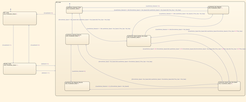
The following figure shows the created Adaptive Cruise Control algorithm as per the requirement:-
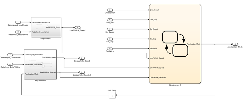
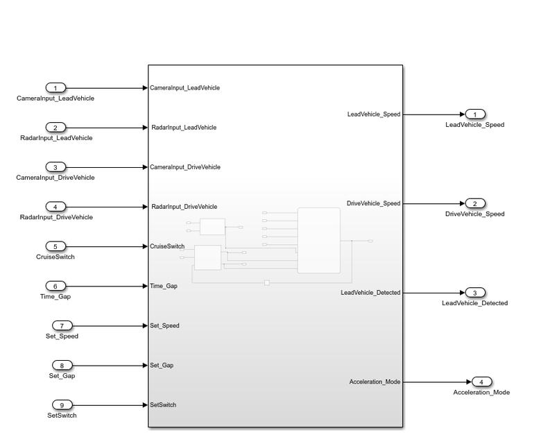
The following figure shows the whole model created for the Adaptive Cruise Control with all input and output ports using Simulink
SLDD:-
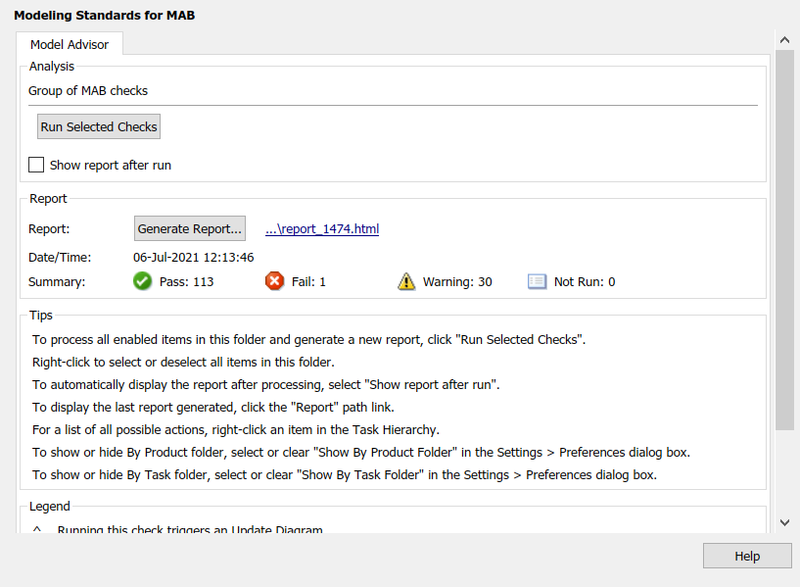
Model Advisor Report:
Code:-
.h file:

/*
 * File: ACC_model.h
 *
 * Code generated for Simulink model 'ACC_model'.
 *
 * Model version                  : 1.3
 * Simulink Coder version         : 9.5 (R2021a) 14-Nov-2020
 * C/C++ source code generated on : Tue Jul  6 12:24:12 2021
 *
 * Target selection: ert.tlc
 * Embedded hardware selection: Intel->x86-64 (Windows64)
 * Code generation objectives: Unspecified
 * Validation result: Not run
 */

#ifndef RTW_HEADER_ACC_model_h_
#define RTW_HEADER_ACC_model_h_
#ifndef ACC_model_COMMON_INCLUDES_
#define ACC_model_COMMON_INCLUDES_
#include "rtwtypes.h"
#endif                                 /* ACC_model_COMMON_INCLUDES_ */

#include "ACC_model_types.h"

/* Macros for accessing real-time model data structure */
#ifndef rtmGetErrorStatus
#define rtmGetErrorStatus(rtm)         ((rtm)->errorStatus)
#endif

#ifndef rtmSetErrorStatus
#define rtmSetErrorStatus(rtm, val)    ((rtm)->errorStatus = (val))
#endif

/* Block states (default storage) for system '<Root>' */
typedef struct {
  uint8_T is_active_c3_ACC_model;      /* '<S1>/Requirement 3' */
  uint8_T is_c3_ACC_model;             /* '<S1>/Requirement 3' */
  uint8_T is_ON_mode;                  /* '<S1>/Requirement 3' */
} DW_ACC_model_T;

/* External inputs (root inport signals with default storage) */
typedef struct {
  real_T CameraInput_LeadVehicle;      /* '<Root>/CameraInput_LeadVehicle' */
  real_T RadarInput_LeadVehicle;       /* '<Root>/RadarInput_LeadVehicle' */
  real_T CameraInput_DriveVehicle;     /* '<Root>/CameraInput_DriveVehicle' */
  real_T RadarInput_DriveVehicle;      /* '<Root>/RadarInput_DriveVehicle' */
  real_T CruiseSwitch;                 /* '<Root>/CruiseSwitch' */
  real_T Time_Gap;                     /* '<Root>/Time_Gap' */
  real_T Set_Speed;                    /* '<Root>/Set_Speed' */
  real_T Set_Gap;                      /* '<Root>/Set_Gap' */
  real_T SetSwitch;                    /* '<Root>/SetSwitch' */
} ExtU_ACC_model_T;

/* External outputs (root outports fed by signals with default storage) */
typedef struct {
  real_T LeadVehicle_Speed;            /* '<Root>/LeadVehicle_Speed' */
  real_T DriveVehicle_Speed;           /* '<Root>/DriveVehicle_Speed ' */
  real_T LeadVehicle_Detected;         /* '<Root>/LeadVehicle_Detected  ' */
  real_T Acceleration_Mode;            /* '<Root>/Acceleration_Mode' */
} ExtY_ACC_model_T;

/* Real-time Model Data Structure */
struct tag_RTM_ACC_model_T {
  const char_T * volatile errorStatus;
};

/* Block states (default storage) */
extern DW_ACC_model_T ACC_model_DW;

/* External inputs (root inport signals with default storage) */
extern ExtU_ACC_model_T ACC_model_U;

/* External outputs (root outports fed by signals with default storage) */
extern ExtY_ACC_model_T ACC_model_Y;

/* Model entry point functions */
extern void ACC_model_initialize(void);
extern void ACC_model_step(void);
extern void ACC_model_terminate(void);

/* Real-time Model object */
extern RT_MODEL_ACC_model_T *const ACC_model_M;

/*-
 * These blocks were eliminated from the model due to optimizations:
 *
 * Block '<S3>/Signal Conversion' : Eliminate redundant signal conversion block
 */

/*-
 * The generated code includes comments that allow you to trace directly
 * back to the appropriate location in the model.  The basic format
 * is <system>/block_name, where system is the system number (uniquely
 * assigned by Simulink) and block_name is the name of the block.
 *
 * Use the MATLAB hilite_system command to trace the generated code back
 * to the model.  For example,
 *
 * hilite_system('<S3>')    - opens system 3
 * hilite_system('<S3>/Kp') - opens and selects block Kp which resides in S3
 *
 * Here is the system hierarchy for this model
 *
 * '<Root>' : 'ACC_model'
 * '<S1>'   : 'ACC_model/Adaptive Cruise Control'
 * '<S2>'   : 'ACC_model/Adaptive Cruise Control/Requirement 1'
 * '<S3>'   : 'ACC_model/Adaptive Cruise Control/Requirement 2'
 * '<S4>'   : 'ACC_model/Adaptive Cruise Control/Requirement 3'
 */
#endif                                 /* RTW_HEADER_ACC_model_h_ */

/*
 * File trailer for generated code.
 *
 * [EOF]
 */
.c file:

/*
 * File: ACC_model.c
 *
 * Code generated for Simulink model 'ACC_model'.
 *
 * Model version                  : 1.3
 * Simulink Coder version         : 9.5 (R2021a) 14-Nov-2020
 * C/C++ source code generated on : Tue Jul  6 12:24:12 2021
 *
 * Target selection: ert.tlc
 * Embedded hardware selection: Intel->x86-64 (Windows64)
 * Code generation objectives: Unspecified
 * Validation result: Not run
 */

#include "ACC_model.h"
#include "ACC_model_private.h"

/* Named constants for Chart: '<S1>/Requirement 3' */
#define ACC_IN_LeadVehicle_Not_Detected ((uint8_T)3U)
#define ACC_model_IN_NO_ACTIVE_CHILD   ((uint8_T)0U)
#define ACC_model_IN_OFF_mode          ((uint8_T)1U)
#define ACC_model_IN_ON_mode           ((uint8_T)2U)
#define ACC_model_IN_Standby_mode      ((uint8_T)3U)
#define IN_LeadVehicle_Detected_Follow ((uint8_T)1U)
#define IN_LeadVehicle_Detected_Resume ((uint8_T)2U)
#define IN_LeadVehicle_Not_Detected_Res ((uint8_T)4U)
#define IN_LeadVehicle_Speed_equal_Set_ ((uint8_T)5U)
#define IN_LeadVehicle_Speed_lessthan_S ((uint8_T)6U)

/* Block states (default storage) */
DW_ACC_model_T ACC_model_DW;

/* External inputs (root inport signals with default storage) */
ExtU_ACC_model_T ACC_model_U;

/* External outputs (root outports fed by signals with default storage) */
ExtY_ACC_model_T ACC_model_Y;

/* Real-time model */
static RT_MODEL_ACC_model_T ACC_model_M_;
RT_MODEL_ACC_model_T *const ACC_model_M = &ACC_model_M_;

/* Model step function */
void ACC_model_step(void)
{
  /* Outputs for Atomic SubSystem: '<Root>/Adaptive Cruise Control' */
  /* Sum: '<S2>/Add' incorporates:
   *  Inport: '<Root>/CameraInput_LeadVehicle'
   *  Inport: '<Root>/RadarInput_LeadVehicle'
   */
  ACC_model_Y.LeadVehicle_Speed = ACC_model_U.CameraInput_LeadVehicle +
    ACC_model_U.RadarInput_LeadVehicle;

  /* Sum: '<S3>/Add' incorporates:
   *  Inport: '<Root>/CameraInput_DriveVehicle'
   *  Inport: '<Root>/RadarInput_DriveVehicle'
   *  UnitDelay: '<S1>/Unit Delay'
   */
  ACC_model_Y.DriveVehicle_Speed = (ACC_model_U.CameraInput_DriveVehicle +
    ACC_model_Y.Acceleration_Mode) + ACC_model_U.RadarInput_DriveVehicle;

  /* Chart: '<S1>/Requirement 3' incorporates:
   *  Inport: '<Root>/CruiseSwitch'
   *  Inport: '<Root>/RadarInput_DriveVehicle'
   *  Inport: '<Root>/SetSwitch'
   *  Inport: '<Root>/Set_Gap'
   *  Inport: '<Root>/Set_Speed'
   *  Inport: '<Root>/Time_Gap'
   *  UnitDelay: '<S1>/Unit Delay'
   */
  if (ACC_model_DW.is_active_c3_ACC_model == 0U) {
    ACC_model_DW.is_active_c3_ACC_model = 1U;
    ACC_model_DW.is_c3_ACC_model = ACC_model_IN_OFF_mode;
    ACC_model_Y.Acceleration_Mode = 0.0;
  } else {
    switch (ACC_model_DW.is_c3_ACC_model) {
     case ACC_model_IN_OFF_mode:
      ACC_model_Y.Acceleration_Mode = 0.0;
      if (ACC_model_U.CruiseSwitch == 1.0) {
        ACC_model_DW.is_c3_ACC_model = ACC_model_IN_Standby_mode;
        ACC_model_Y.Acceleration_Mode = 1.0;
      }
      break;

     case ACC_model_IN_ON_mode:
      if (ACC_model_U.CruiseSwitch == 0.0) {
        ACC_model_DW.is_ON_mode = ACC_model_IN_NO_ACTIVE_CHILD;
        ACC_model_DW.is_c3_ACC_model = ACC_model_IN_OFF_mode;
        ACC_model_Y.Acceleration_Mode = 0.0;
      } else if (ACC_model_U.SetSwitch == 0.0) {
        ACC_model_DW.is_ON_mode = ACC_model_IN_NO_ACTIVE_CHILD;
        ACC_model_DW.is_c3_ACC_model = ACC_model_IN_Standby_mode;
        ACC_model_Y.Acceleration_Mode = 1.0;
      } else {
        switch (ACC_model_DW.is_ON_mode) {
         case IN_LeadVehicle_Detected_Follow:
          ACC_model_Y.Acceleration_Mode = 2.0;
          if (ACC_model_U.RadarInput_DriveVehicle == 0.0) {
            ACC_model_DW.is_ON_mode = ACC_IN_LeadVehicle_Not_Detected;
            ACC_model_Y.Acceleration_Mode = 1.0;
          } else if (((ACC_model_U.RadarInput_DriveVehicle == 1.0) &&
                      (ACC_model_Y.LeadVehicle_Speed < ACC_model_U.Set_Speed)) ||
                     (ACC_model_U.Time_Gap < ACC_model_U.Set_Gap)) {
            ACC_model_DW.is_ON_mode = IN_LeadVehicle_Speed_lessthan_S;
            ACC_model_Y.Acceleration_Mode = 4.0;
          }
          break;

         case IN_LeadVehicle_Detected_Resume:
          ACC_model_Y.Acceleration_Mode = 3.0;
          if ((ACC_model_Y.DriveVehicle_Speed < ACC_model_U.Set_Speed) &&
              (ACC_model_Y.LeadVehicle_Speed > ACC_model_Y.DriveVehicle_Speed) &&
              (ACC_model_U.Time_Gap >= ACC_model_U.Set_Gap)) {
            ACC_model_DW.is_ON_mode = IN_LeadVehicle_Speed_equal_Set_;
            ACC_model_Y.Acceleration_Mode = 5.0;
          } else if ((ACC_model_Y.DriveVehicle_Speed == ACC_model_U.Set_Speed) &&
                     (ACC_model_Y.LeadVehicle_Speed >= ACC_model_U.Set_Speed) &&
                     (ACC_model_U.Time_Gap >= ACC_model_U.Set_Gap)) {
            ACC_model_DW.is_ON_mode = IN_LeadVehicle_Detected_Follow;
            ACC_model_Y.Acceleration_Mode = 2.0;
          } else if (ACC_model_U.RadarInput_DriveVehicle == 0.0) {
            ACC_model_DW.is_ON_mode = IN_LeadVehicle_Not_Detected_Res;
            ACC_model_Y.Acceleration_Mode = 1.0;
          }
          break;

         case ACC_IN_LeadVehicle_Not_Detected:
          ACC_model_Y.Acceleration_Mode = 1.0;
          if ((ACC_model_U.RadarInput_DriveVehicle == 1.0) &&
              (ACC_model_Y.DriveVehicle_Speed == ACC_model_U.Set_Speed) &&
              (ACC_model_Y.LeadVehicle_Speed >= ACC_model_U.Set_Speed) &&
              (ACC_model_U.Time_Gap >= ACC_model_U.Set_Gap)) {
            ACC_model_DW.is_ON_mode = IN_LeadVehicle_Detected_Follow;
            ACC_model_Y.Acceleration_Mode = 2.0;
          } else if (((ACC_model_U.RadarInput_DriveVehicle == 1.0) &&
                      (ACC_model_Y.LeadVehicle_Speed < ACC_model_U.Set_Speed)) ||
                     (ACC_model_U.Time_Gap < ACC_model_U.Set_Gap)) {
            ACC_model_DW.is_ON_mode = IN_LeadVehicle_Speed_lessthan_S;
            ACC_model_Y.Acceleration_Mode = 4.0;
          }
          break;

         case IN_LeadVehicle_Not_Detected_Res:
          ACC_model_Y.Acceleration_Mode = 1.0;
          break;

         case IN_LeadVehicle_Speed_equal_Set_:
          ACC_model_Y.Acceleration_Mode = 5.0;
          if ((ACC_model_U.RadarInput_DriveVehicle == 0.0) ||
              (ACC_model_Y.DriveVehicle_Speed <= ACC_model_U.Set_Speed)) {
            ACC_model_DW.is_ON_mode = IN_LeadVehicle_Not_Detected_Res;
            ACC_model_Y.Acceleration_Mode = 1.0;
          } else if (((ACC_model_Y.DriveVehicle_Speed < ACC_model_U.Set_Speed) &&
                      (ACC_model_Y.LeadVehicle_Speed >
                       ACC_model_Y.DriveVehicle_Speed)) || (ACC_model_U.Time_Gap
                      >= ACC_model_U.Set_Gap)) {
            ACC_model_DW.is_ON_mode = IN_LeadVehicle_Detected_Resume;
            ACC_model_Y.Acceleration_Mode = 3.0;
          } else if (((ACC_model_Y.LeadVehicle_Speed < ACC_model_U.Set_Speed) &&
                      (ACC_model_Y.LeadVehicle_Speed <
                       ACC_model_Y.DriveVehicle_Speed)) || (0.75 *
                      ACC_model_U.Set_Gap == ACC_model_U.Time_Gap)) {
            ACC_model_DW.is_ON_mode = IN_LeadVehicle_Speed_lessthan_S;
            ACC_model_Y.Acceleration_Mode = 4.0;
          }
          break;

         default:
          /* case IN_LeadVehicle_Speed_lessthan_Set_Speed: */
          ACC_model_Y.Acceleration_Mode = 4.0;
          if ((ACC_model_U.RadarInput_DriveVehicle == 0.0) &&
              (ACC_model_Y.DriveVehicle_Speed == ACC_model_U.Set_Speed)) {
            ACC_model_DW.is_ON_mode = ACC_IN_LeadVehicle_Not_Detected;
            ACC_model_Y.Acceleration_Mode = 1.0;
          } else if ((ACC_model_Y.LeadVehicle_Speed * 1.25 >=
                      ACC_model_Y.DriveVehicle_Speed) &&
                     (ACC_model_Y.LeadVehicle_Speed * 0.75 <=
                      ACC_model_Y.DriveVehicle_Speed) &&
                     (ACC_model_Y.DriveVehicle_Speed < ACC_model_U.Set_Speed) &&
                     (ACC_model_U.Time_Gap <= 1.25 * ACC_model_U.Set_Gap) &&
                     (ACC_model_U.Time_Gap >= 0.75 * ACC_model_U.Set_Gap)) {
            ACC_model_DW.is_ON_mode = IN_LeadVehicle_Speed_equal_Set_;
            ACC_model_Y.Acceleration_Mode = 5.0;
          }
          break;
        }
      }
      break;

     default:
      /* case IN_Standby_mode: */
      ACC_model_Y.Acceleration_Mode = 1.0;
      if (ACC_model_U.CruiseSwitch == 0.0) {
        ACC_model_DW.is_c3_ACC_model = ACC_model_IN_OFF_mode;
        ACC_model_Y.Acceleration_Mode = 0.0;
      } else if (ACC_model_U.SetSwitch == 1.0) {
        ACC_model_DW.is_c3_ACC_model = ACC_model_IN_ON_mode;
        ACC_model_DW.is_ON_mode = IN_LeadVehicle_Detected_Follow;
        ACC_model_Y.Acceleration_Mode = 2.0;
      }
      break;
    }
  }

  /* End of Chart: '<S1>/Requirement 3' */
  /* End of Outputs for SubSystem: '<Root>/Adaptive Cruise Control' */

  /* Outport: '<Root>/LeadVehicle_Detected  ' incorporates:
   *  Inport: '<Root>/RadarInput_DriveVehicle'
   */
  ACC_model_Y.LeadVehicle_Detected = ACC_model_U.RadarInput_DriveVehicle;
}

/* Model initialize function */
void ACC_model_initialize(void)
{
  /* (no initialization code required) */
}

/* Model terminate function */
void ACC_model_terminate(void)
{
  /* (no terminate code required) */
}

/*
 * File trailer for generated code.
 *
 * [EOF]
 */
Conclusion:
Thus, a Simulink Data Dictionary file has been created, an algorithm for Adaptive Cruise Control has been made, and the C code for the model has been generated using Simulink satisfactorily.
Leave a comment
Thanks for choosing to leave a comment. Please keep in mind that all the comments are moderated as per our comment policy, and your email will not be published for privacy reasons. Please leave a personal & meaningful conversation.
Other comments...
Be the first to add a comment
Read more Projects by Parvez Khan (19)
Project 2-Highway Assistant-Lane Changing Assistant
Aim: To develop an algorithm for one of the features of the Highway Lane Changing Assistance, create a Simulink Data Dictionary for the given signals data list, develop a Model Advisor Report and generate a C code for it using Autosar coder in Simulink. Objectives: The model must be developed in MATLAB Simulink per MBD…

22 Oct 2021 06:55 PM IST
Project 1- Traffic Jam Assistant Feature
Aim: To create a Simulink Data Dictionary, develop an algorithm for one of the features of Traffic Jam Assistance and generate a C code for it using Simulink. Objective: Model Development as per MBD guidelines. Creation of Simulink Data Dictionary. Code Generation using Embedded Coder. Generating Model Advisor Report.…
19 Oct 2021 07:21 AM IST
Project 2 Adaptive Cruise Control
Aim: To create a Simulink Data Dictionary, develop an algorithm for Adaptive Cruise Control and generate a C code for it using Simulink. Objective: 1. Developing Adaptive Cruise Control feature as per the Requirement Document using MATLAB Simulink. 2. Follow all the MBD-related processes: Requirement…
16 Oct 2021 07:11 AM IST
Project 1 (Mini Project on Vehicle Direction Detection
Mini project on Vehicle direction detection Aim:- To create a Vehicle direction determination model for given requirements. Objective:- Development of MATLAB Simulink model as per requirements. Tad the requirements to the Simulink model. MBD compliant changes, Data Dictionary creation, and code generation is added advantages…
10 Oct 2021 11:57 AM IST
Related Courses


8 Hours of Content
Skill-Lync offers industry relevant advanced engineering courses for engineering students by partnering with industry experts.


Our Company

4th Floor, BLOCK-B, Velachery - Tambaram Main Rd, Ram Nagar South, Madipakkam, Chennai, Tamil Nadu 600042.

Top Individual Courses
Top PG Programs
Skill-Lync Plus
Trending Blogs
© 2025 Skill-Lync Inc. All Rights Reserved.