


Courses by Software
Courses by Semester
Courses by Domain
Tool-focused Courses
Machine learning
POPULAR COURSES
Success Stories

Photo Realistic Rendering
MODELING OF AMERICAN CHOPPER USING SOLIDWORKS OBJECTIVE : To design AMERICAN CHOPPER by using given blue prints with surface…
DHANASEKARAN A
updated on 16 May 2022


MODELING OF AMERICAN CHOPPER USING SOLIDWORKS
OBJECTIVE :
To design AMERICAN CHOPPER by using given blue prints with surface & solid modelling techniques.
INTRODUCTION :
In this course we learn advanced surface modelling techniques in SOLIDWORKS. We use bule prints to create outer sketch of the american chopper and then we use various surface and solid modelling techniques. Then the surface and solidmodeling parts well assembled in assembly workbech and rendered as final output.
DESIGN METHODOLOGY :

TRANSMISSION BELT :
A belt drive is a transmission system that uses a flexible strip to transfer power.
_1646832210.png)
KICK STAND :
A kickstand is a device on a bicycle or motorcycle that allows the bike to be kept upright without leaning against another object.
_1646832323.png)
FRONT FENDER :
Fenders are what will keep you from having a skunk stripe on your backside.
_1646832401.png)
REAR FENDER :
Its primary purpose is to prevent sand, mud, rocks, liquids, and other road spray from being thrown into the air by the rotating tire.
_1646832515.png)
OIL TANK :
Oil tank is used to store the oil to run engine system and lubrication parts.
_1646940059.png)
CHAIN :
Modern bike chains are properly called 'roller chains', and consist of short cylindrical rollers held together by side links. The gaps between the rollers mesh with the teeth on a sprocket or chainring, to drive the transmission when turned.
_1646940922.png)
PEDAL :
Pedal is used to place the leg on that which is used to give comfort to the rider.
_1646940110.png)
FRONT WHEEL :
Fork - the two-legged part of the frame that holds the front wheel in place. The steerer tube is a part of the fork that extends up into the frame through the head tube.
_1649067059.png)
REAR WHEEL :
Rear wheel which is used to move wheel by transmiting power from the engine with the help of chain which is connected to the sprocket on the rear wheel.
_1649362948.png)
FRONT FORK :
Most forks incorporate the front suspension and front brake, and allow the front wheel to rotate about the steering axis so that the bike may be steered.

CHASSIS :
A motorcycle's chassis or frame forms its skeleton. All the components of a motorcycle, like the suspension, wheels, fuel tank, seats, handlebars etc, are attached to this base structure which lends a motorcycle its strength and ability to handle well.
_1649241725.png)
ENGINE :
A machine for converting any of various forms of energy into mechanical force and motion
_1649241410.png)
GAS TANK :
A fuel tank (also called a petrol tank or gas tank) is a safe container for flammable fluids.
_1649502520.png)
DESCRIPITION OF FEATURES :
LOFT SURFACE:
Loft Surfaces are surfaces generated by multiple 3D Curves or existing edges creating a smooth tangency between the selected curves. Match Points are created between each selection denoting the orientation and path of the loft surface.

SURFACE TRIM:
surface, plane, or sketch as a trim tool to trim intersecting surfaces. You can also use a surface in conjunction with additional surfaces, as mutual trim tools.

SURFACE FILL:
The Filled Surface feature constructs a surface patch with any number of sides, within a boundary defined by existing model edges, sketches, or curves, including composite curves.

SURFACE KNIT:
Knit Surface tool to combine two or more faces and surfaces into one.
SURFACE CUT:
Surface cut a solid model by removing material with a surface or plane. With multibody parts, you can select which bodies to keep.

EXTRUDE:
Extrude tool is used to extend a sketched profile in one or two directions as either a thin feature or a solid feature. An extrude operation can either add material to a part (in a base or boss) or remove material from a part.

CUT EXTRUDE:
Extruded cut feature removes material from the part.
REVOLVE BOSS BASE:
To create a revolve feature: Create a sketch that contains one or more profiles and a centerline, line, or edge to use as the axis around which the feature revolves. Click one of the following revolve tools.

FILLET:
Fillets describe rounded corners of a design (or part) that help to reduce stresses and prevent rapid deformation at the corners of the part.

CHAMFER:
A chamfer is the sloped or angled edges or corners of a part design. It is an antonym of the fillet. Instead of having a curved shape, a chamfer is straight and has a sharp angle.

LINEAR PATTERN:
Linear patterns to create multiple instances of one or more features that you can space uniformly along one or two linear paths.
CIRCULAR PATTERN:
Circular patterns to create multiple instances of one or more features that you can space uniformly around an axis.
MOVE/COPY SOLID BODIES:
It is used to move, rotate, and copy solid and surface bodies, or place them using mates.

PROJECTED CURVE:
Create a Curve as the intersection of two projected sketches. Note that the projections from one sketch must intersect the other in one contiguous curve for this operation to succeed.

SPLIT LINE:
The Split Line. tool projects an entity (sketch, solid, surface, face, plane, or surface spline) to surfaces, or curved or planar faces. It divides a selected face into multiple separate faces.

CONVERT ENTITIES:
Whenever we need to make a sketch entity that matches other geometry of our model we can use the Convert Entities tool.

DOME :
Dome creates a dome that is tangent to the adjacent cylindrical or conical face.
COMBINE :
It is used to add two or more solid and surface bodies into a single body.

OFFSET SURFACE :
The offset surface tool is useful way of creating a series of deposit or erosion contact surfaces from a reference mesh
MIRROR:
Create an opposite-hand version of a part. In a part select a face or plane to mirror about.

FILL SURFACE :
The Filled Surface feature constructs a surface patch with any number of sides, within a boundary defined by existing model edges, sketches, or curves, including composite curves.

SHELL :
The shell tool hollows out a part, leaves open the faces you select, and creates thin-walled features on the remaining faces. If you do not select any face on the model, you can shell a solid part, creating a closed, hollow model.

SWEEP CUT :
Creates a sweep by moving a 2D profile along a 2D or 3D sketch path. Profile. Sets the profile (section) used to create the sweep.

ASSEMBLY :
You can build complex assemblies consisting of many components, which can be parts or other assemblies, called subassemblies. For most operations, the behavior of components is the same for both types. Adding a component to an assembly creates a link between the assembly and the component.
TOP DOWN ASSEMBLY :
In top-down assembly design, one or more features of a part are defined by something in an assembly, such as a layout sketch or the geometry of another part.
BOTTOM UP ASSEMBLY :
Bottom-up design is the traditional method. You first design and model parts, then insert them into an assembly and use mates to position the parts. To change the parts, you must edit them individually.
_1649502768.png)
_1649502790.png)
_1649502814.png)
_1649502834.png)
RENDERING :
PhotoView 360 is a SOLIDWORKS add-in that produces photo-realistic renderings of SOLIDWORKS models. The rendered image incorporates the appearances, lighting, scene, and decals included with the model.


CONCLUSION:
The AMERICAN CHOPPER designed successfully by using surface and solid modelling in solid works and assembled in assembly workbech successfully and rendered in solidworks visualize.
Leave a comment
Thanks for choosing to leave a comment. Please keep in mind that all the comments are moderated as per our comment policy, and your email will not be published for privacy reasons. Please leave a personal & meaningful conversation.
Other comments...
Be the first to add a comment
Read more Projects by DHANASEKARAN A (8)
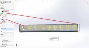
Week 9 - Challenge 2 - Switch Bezel Design
Tooling Axis Creation Take the class A surface Extract the bottom face and create the Origin Point Choose the Line command and make the axis normal to the Extracted surface. But in the bisection method, there are some errors during the draft analysis of the sidewall. Select the YZ plane and position…

27 Jun 2023 10:25 AM IST
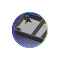
Week 9 - Challenge 1 - Base Bracket Design
METHOD FOR DRAFT ANALYSIS - First I checked the possible direction for the draft analysis in my case the z-direction was the best possible way to take the draft analysis, then I created the dummy tooling axis for the reference of x,y,z-direction.then took a plane in refrence to yz-plane and took a intersection in…
24 Jun 2023 05:37 PM IST
Underbody Coating
UNDERBODY COATING OBJECTIVE : To learn about underbody coating in the view of automobile and other general parts, also why underbody coating, types of under bodycoating in brief. INTRODUCTION : An undercoat is used after a primer. It is used to…
18 May 2022 06:33 PM IST
Benchmarking
BENCHMARKING OBJECTIVE : …
18 May 2022 11:27 AM IST
Related Courses


Skill-Lync offers industry relevant advanced engineering courses for engineering students by partnering with industry experts.


Our Company

4th Floor, BLOCK-B, Velachery - Tambaram Main Rd, Ram Nagar South, Madipakkam, Chennai, Tamil Nadu 600042.

Top Individual Courses
Top PG Programs
Skill-Lync Plus
Trending Blogs
© 2025 Skill-Lync Inc. All Rights Reserved.