


Courses by Software
Courses by Semester
Courses by Domain
Tool-focused Courses
Machine learning
POPULAR COURSES
Success Stories

Boeing-747 _ Final_Project
DESIGN OF BOEING 747-8 AIRCRAFT BY USING SOLID WORKS OBJECTIVE: The main objective of this project is to model boeing 747-8 by using solidmodeling…
DHANASEKARAN A
updated on 08 Jan 2022


DESIGN OF BOEING 747-8 AIRCRAFT BY USING SOLID WORKS
OBJECTIVE:
The main objective of this project is to model boeing 747-8 by using solidmodeling and surface modeling
INTRODUCTION :
The boeing 747-8 is a wide body airliner developed by boeing commercial airplanes the latest and largest varient of the 747. After introducing the 747-400 boeing considered larger 747 versions as alternatives to airbus A3xx. The streched 747 advanced was launched as the 747-8 on november 14-2005 for a market forecast of 300 aircraft. The first 747-8F freighter performed its maiden flight on february-8 ,2010 and the passenger 747-8i intercontinental followed suit on march 20, 2011. The cargo version was fiest deliverd in october-2011 and the airliner began commerical service in june 2012.
The 747-8 war the first lengthened 747 to go into production and the second 747 version with a fuselage of modified length after the shortened 747SP.
| WING SPAN | 68.45m |
| LENGTH | 76.25m |
| HEIGHT | 19.35m |
| POWER PLANT | 4xGEnx-2B67 (296.7KN) |
Table Technical Data Listed Below.
DESIGN METHODOLOGY:

BLUE PRINT:
The sketch picture option the images are inserted and the required dimensions.
_1640681194.png)
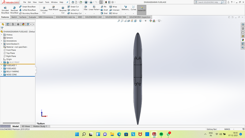
Blue print setup for main body of fuselage to livery.
FUSELAGE:
- Fuselage is the central portion of the body of an airplane, designed to accommodate the crew, passengers, and cargo. It varies gratly in design and size according to the function of the aircraft.
The predominant types of fuselage structures are the monocoque ( kind of construction in which the outer skin bears a major part or all of the stresses) and semimonocoque. These structures provide better strength-to-weight ratios for the fuselage covering than the truss-type construction used in earlier planes.
_1638809547_1640682534.png)
BELLY FAIRING:
- In an aircraft comprising a fuselage and a belly fairing the fairing is made of two independent parts. For example, a first part of the fairing comprises a front section a central section and a first portion of a rear section.
- A second part of the fairing comprises a second portion of the rear section. The second part can shift relative to the first part of the fairing.
- Also disclosed is a belly fairing for aircraft comprising two independent parts. It can also cover additional cargo storage or fuel tanks.
NOSE CONE:
- Found at the foremost point of an aircraft a nose cone must be aerodynamic in order to reduce drag on a plane.
- On most commercial and military aircraft the nose cone also houses radar and other instruments that might be used to detect meteorological phenomena, track enemy aircraft or transmit communication signals.

PITOT TUBES:
- Basically a pitot tube is used in wind tunnel experiments and on airplanes to measure flow speed. Its a slender tube that has two holes on it.
- The front hole is placed in the airstream to measure what's called the stagnation pressure.
- The side hole measures the static pressure. By measuring the difference between these pressures, you get the dynamic pressure, which can be used to calculate airspeed.
- On an airplane, the pitot tube can be mounted in a number of ways, including jutting out from the edge of the wing or sticking up from the fuselage.

COCKPIT WINDOWS:
- A cockpit or flight deck is the area, usually near the front of an aircraft or spacecraft, from which a pilot controls the aircraft.
- The cockpit of an aircraft contains flight instruments on an instrument panel, and the controls that enable the pilot to fly the aircraft. In most airliners, a door separates the cockpit from the aircarft cabin.
- Cockpit windows may be equipped with a sun shield. Most cockpits have windows that can be opened when the aircraft is on the ground.
- Nearly all glass windows in large aircraft have an anti-reflective coating and an internal heating element to melt ice. Smaller aircraft may be equipped with a transparent aircraft canpoy.

WINDSHIELD WIPERS:
- Windshield wipers are the most common rain protection feature.
- Most of them use electrical motors but some aircraft may be equipped with hydraulic wiper motors.
- Usually the pilot’s and copilot’s windshield wipers are operated by separate systems to ensure that clear vision is maintained through one of the windows should one system fail.
- Each windshield wiper assembly consists of a wiper, wiper arm, and a wiper motor/converter.
- In many cases, windshield wiper systems will have limiting airspeed, above which they must not be operated.
- This limitation is due to the increased slipstream loading on, and the potential of damage to, the wiper assembly at higher speeds.

PASSENGER WINDOWS:
A cabin window consists of three panes:
1) an outer pane flush with the outside fuselage
2) an inner pane — which has a little hole in it you may have spotted, and
3) a thinner, non-structural plastic pane called a scratch pane.
Passengers can’t touch the inner pane (the one with the hole in it) or the outer pane for safety reasons. Instead, passengers can rest their weary heads against the scratch pane, press their iPhone against it, or simply muck it up with greasy fingers.

DOORS AND HATCHES:
- Passengers board or exit from the plane through these doors. Specially engineered exit doors are designed so that they do not open during the flight and do not cause pressure loss.
- There are three types of doors on a plane: the passenger exits, the service doors, and the emergency exits.
- The passenger doors used during the boarding are especially located at the front, middle and rear sections of large passenger aircraft.

LIGHTS AND ANTENNAS:
- Anti-collision lights, also known as Beacon lights or Strobe lights are a set of lights required on every aircraft to improve visibility to others, as well as collision avoidance measures by warning other pilots. Historically they have used incandescent bulbs, but recently Light-emitting diodes have been used.
- Antennas are commonly used for transponders and distance measuring equipment (DME), and they are always found on the bottom of the aircraft.
- They are about four inches long, and the same antenna can be used for both systems because the transponder frequency is in the middle of the DME frequency band.
- Dipole antenna.
- Marconi antenna.
- Loop antenna.

AUXILIARY POWER UNIT:
- An auxiliary power unit (APU) is a device on a vehicle that provides energy for functions other than propulsion.
- They are commonly found on large aircraft and naval ships as well as some large land vehicles.
- Aircraft APUs generally produce 115 V AC voltage at 400 Hz (rather than 50/60 Hz in mains supply), to run the electrical systems of the aircraft others can produce 28 V DC voltage.
- APUs can provide power through single or three-phase systems.

VERTICAL STABILIZERS:
- A vertical stabilizer or tail fin is the static part of the vertical tail of an aircraft.
- The term is commonly applied to the assembly of both this fixed surface and one or more movable rudders hinged to it.
- Their role is to provide control, stability and trim in yaw (also known as directional or weathercock stability). It is part of the aircraft specifically of its stabilizer
- The vertical tail is typically mounted on top of the rear fuselage, with the horizontal stabilizers mounted on the side of the fuselage (a configuration termed "conventional tail"). Other configurations, such as T-tail or twin tail, are sometimes used instead.
- The vertical stabilizer keeps the nose of the plane from swinging from side to side, which is called yaw.

HORIZONTAL STABILIZER:
- The stabilizer is a fixed wing section whose job is to provide stability for the aircraft to keep it flying straight.
- The horizontal stabilizer prevents up-and-down, or pitching, motion of the aircraft nose.
- A horizontal stabilizer is used to maintain the aircraft in longitudinal balance, or trim it exerts a vertical force at a distance so the summation of pitch moments about the center of gravity is zero.
- The vertical force exerted by the stabilizer varies with flight conditions, in particular according to the aircraft lift coefficient and wing flaps deflection which both affect the position of the centre of pressure, and with the position of the aircraft center of gravity (which changes with aircraft loading and fuel consumption).
- This maintains a constant aircraft attitude, with unchanging pitch angle relative to the airstream, without active input from the pilot.

WINGS:
- Wing, in aeronautics, an airfoil that helps lift a heavier-than-air craft.
- When positioned above the fuselage (high wings) wings provide an unrestricted view below and good lateral stability.
- Low wing: mounted near or below the bottom of the fuselage.
- Mid wing: mounted approximately halfway up the fuselage.
- Shoulder wing mounted on the upper part or shoulder of the fuselage, slightly below the top of the fuselage.
- High wing: mounted on the upper fuselage.

FLAPS AND AILERONS:
- An aileron ( little wing or fin) is a hinged flight control surface usually forming part of the trailing edge of each wing of a fixed wing aircraft.
- Ailerons are used in pairs to control the aircraft in roll (or movement around the aircraft's longitudinal axis), which normally results in a change in flight path due to the tilting of the lift vector.
- Movement around this axis is called rolling or banking.

FLAP TRACK FAIRINGS:
- Fairings are needed to enclose the flap operating mechanism when the flap is up.
- They open up as the flap comes down and may also pivot to allow the necessary sideways movement of the extending mechanism which occurs on swept-wing installations.

LANDING GEAR HATCHES OPENED CLOSED:
- Landing gear is the undercarriage of an aircraft or spacecraft and may be used for either takeoff or landing. For aircraft it is generally needed for both
- For aircraft, the landing gear supports the craft when it is not flying, allowing it to take off, land, and taxi without damage. Wheeled landing gear is the most common, with skis or floats needed to operate from snow,ice,water and skids for vertical operation on land. Faster aircraft have retractable undercarriages, which fold away during flight to reduce drag.
- Generally, Landing Gears in a Commercial Airliner are Extended at approximately 1800 ft AGL (Above Ground Level) when the Airspeed is less than 190 KIAS, before the 'Final' Phase of the Flight.


ENGINE:
- An aircraft engine, often referred to as an aero engine, is the power component of an aircraft propulsion system.
- Most aircraft engines are either piston engines or gas turbines, although a few have been rocket powered and in recent years many small UAVs have used electric motors.
- Types of Airplane Engines
- Turbojet
- Turboprop
- Tubofan
- The engine selected for this air craft GEnx2B67

LIVERY:
- An aircraft livery is a set of comprehensive insignia comprising color, graphic, and typographical identifiers which operators (airlines, governments, airforces and occasionally private and corporate owners) apply to their aircraft.

NOSE GEAR ASSEMBLY:
- Nose gear is the name given to the landing gear in the nose of an airplane.
- In most airplane designs, the nose gear is used to steer the airplane while it is on the ground.
- In tail-dragger designs, the airplane is turned by applying the brake in the direction that the pilot wants the plane to turn.


MAIN GEAR ASSEMBLY:
- Main landing gear are the two or more large gear located close to the aircraft's center of gravity.
- Three basic arrangements of landing gear are used tail wheeltype landing gear (also known as conventional gear), tandem landing gear, and tricycle-type landing gear
- Main gear assembly consist of two suspension arm and wheels.

BOEING 747-8 ASSEMBLY:
- After completing the livery the main body (fuselage) are inserted into the assembley environment.
- The engine is assembled with the main body by applying coincidence and distance mate between the engine and fuselage body.
- There are different types of mates
- coincidence mate
- concentric mate
- Distance mate
- Angular mate
- Gear mate


DESCRIPTION OF TOOLS:
- Right, Top, Front Planes: These are the planes used for creating sketches.
- Line: This command is used to draw line, curve,etc
- Spline: This command is used to create spline on the sketches we can draw into any shape that we required
- Rectangle: This command is used to draw rectangle at required sketch.
- Circle: This command is used to draw the circle in a required diameter
- Point: This command is used to keep the point for reference of the sketch
- Offset: This command is used for offseten the drawn sketch to the given dimension
- Smart dimension: This command is used to define the dimension of the sketch.
- Convert entities: create one or more curves in a sketch by projecting an edge, loop, face, curve, or external sketch contour, set of edges, or set of sketch curves onto the sketch plane.
- Mirror entities: Mirror Entities to mirror pre-existing 2D sketch entities on a plane, and then select the entity about which to mirror. If you want to first select the entity about which to mirror, and then sketch the entities to mirror
- Split Line: projects an entity (sketch, solid, surface, face, plane, or surface spline) to surfaces, or curved or planar faces. It divides a selected face into multiple separate faces.
- Project curves: Create a sketch on each of two intersecting planes, closing each sketch
- Planes: This planes are created by using reference command
- Axis: This command is used to create reference sketch.
FEATURES:
- Extrude Boss Basse: An Extruded Boss/Base feature will allow you to take a 2D sketch and add thickness to it in the third dimension. Every few releases, this feature gets some terrific functionality added to it.
- Revolved Boss Base: Revolves add or remove material by revolving one or more profiles around a centerline.
- Lofted Boss: Loft creates a feature by making transitions between profiles. A loft can be a base, boss, cut, or surface.
- Extruded cut: create an extruded cut in a two-dimensional or axisymmetric planar part by sketching the two-dimensional cross-section of the cut directly on the plane of the part.
- The cut always passes completely through the part.
- Shell: The shell tool hollows out a part, leaves open the faces you select, and creates thin-walled features on the remaining faces.
- Mirror: Mirroring is another way that SolidWorks can create a copy of an existing object. Additionally, you must choose a plane to mirror parts.


- CONCLUSION:
- In this project the various parts of the boeing 747-8 was modeled with the different environments surface modeleing, solid modeleing and assembly availabile in the solidworks.
- The Assembly of the boeing 747-8 is rendered with photoview 360 and solidworks visualize to create a real view of the model with the environment.
Leave a comment
Thanks for choosing to leave a comment. Please keep in mind that all the comments are moderated as per our comment policy, and your email will not be published for privacy reasons. Please leave a personal & meaningful conversation.
Other comments...
Be the first to add a comment
Read more Projects by DHANASEKARAN A (8)
Week 9 - Challenge 2 - Switch Bezel Design
Tooling Axis Creation Take the class A surface Extract the bottom face and create the Origin Point Choose the Line command and make the axis normal to the Extracted surface. But in the bisection method, there are some errors during the draft analysis of the sidewall. Select the YZ plane and position…

27 Jun 2023 10:25 AM IST
Week 9 - Challenge 1 - Base Bracket Design
METHOD FOR DRAFT ANALYSIS - First I checked the possible direction for the draft analysis in my case the z-direction was the best possible way to take the draft analysis, then I created the dummy tooling axis for the reference of x,y,z-direction.then took a plane in refrence to yz-plane and took a intersection in…
24 Jun 2023 05:37 PM IST
Underbody Coating
UNDERBODY COATING OBJECTIVE : To learn about underbody coating in the view of automobile and other general parts, also why underbody coating, types of under bodycoating in brief. INTRODUCTION : An undercoat is used after a primer. It is used to…
18 May 2022 06:33 PM IST
Benchmarking
BENCHMARKING OBJECTIVE : …
18 May 2022 11:27 AM IST
Related Courses


Skill-Lync offers industry relevant advanced engineering courses for engineering students by partnering with industry experts.


Our Company

4th Floor, BLOCK-B, Velachery - Tambaram Main Rd, Ram Nagar South, Madipakkam, Chennai, Tamil Nadu 600042.

Top Individual Courses
Top PG Programs
Skill-Lync Plus
Trending Blogs
© 2025 Skill-Lync Inc. All Rights Reserved.