


Courses by Software
Courses by Semester
Courses by Domain
Tool-focused Courses
Machine learning
POPULAR COURSES
Success Stories

Assignment 6-Frontal Crash Simulation Challenge
Frontal Crash test AIM: Frontal car crash simulation of Dodge Neon BIW using RADIOSS solver and Preprocessing using HyperMesh / HyperCrash. OBJECTIVE: The following are the requirements for this project: Set the model of the Neon Dodge ie, the FEA model, so that the required output requests can be post-processed from it. …
MD SUBHAN
updated on 02 Jul 2023


Frontal Crash test
AIM:
Frontal car crash simulation of Dodge Neon BIW using RADIOSS solver and Preprocessing using HyperMesh / HyperCrash.
OBJECTIVE:
The following are the requirements for this project:
- Set the model of the Neon Dodge ie, the FEA model, so that the required output requests can be post-processed from it.
- Sectional force in the rails at the location of indicated node 174247.
- The axial force received on the rails from the bumper.
- Shotgun cross-sectional forces.
- A pillar cross-section.
- Acceleration curve received on the accelerometer at base of B pillar (on B pillar rocker).
- Intrusions on the dash wall 66695, 66244.
SETUP REQUESTS:
- Check the unit system and either follow [Mg mm s] or [Kg mm ms].
- Create an appropriate interface, friction 0.2, and recommended parameters.
- Make sure of no penetrations and intersections.
- Correct rigid bodies if any issues.
- Create a rigid wall with friction 0.1.
- Compare the model weight with the full-scale 300k nodes model and use added masses to reach the target weight of 700kg while getting CG about the required range.
- Initial velocity 35 mph.
- Use a model checker to ensure good quality.
- Time-step: 0.5 to 0.1 microseconds.
- Run 80 ms
OUTPUT REQUESTS:
- Sectional force in the rails at the location of indicated node 174247.
- The axial force received on the rails from the bumper.
- Shotgun cross-sectional forces.
- A pillar cross-section.
- Acceleration curve received on the accelerometer at base of B pillar (on B pillar rocker).
- Intrusions on the dash wall 66695, 66244.
Procedure:
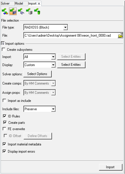
Import the model:
Import the '.rad' starter file of the model,' neon_front_0000.rad' in Radioss using Import Solver Deck option.
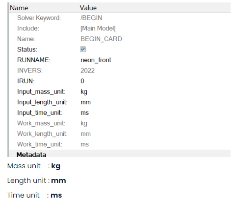
Check unit system and either follow[Mg mm s] or [Kg mm ms].
Unit System:
For units, browse
Model > Cards > BEGIN_CARD
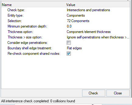
Make sure of no penetrations and intersection.
for Intersection penetrations.
_1687869979.png)
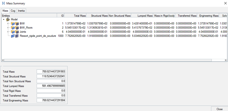
Compare the model weight with the full scale 300k nodes model and use added masses to reach target weight 700kg while getting CG about the required range.
To compare the model weight with the full scale 300k nodes model and use added masses to reach target weight 700kg while getting CG about the required range. Check by using Tools > Mass Details > Mass, cog and inertia and check the mass.
Existing weight of mesh geometry: 188 kg
Required weight : 700 kg
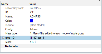
Additional mass to be added: 512 kg
To add additional weight to achive the required weight ,
Go to Solver and click on create select ADMAS create a new card now put the value of added mass 512kg & select grnd_ID as shown in below image.
following is the achived COG location,
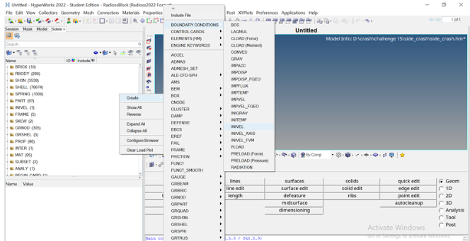
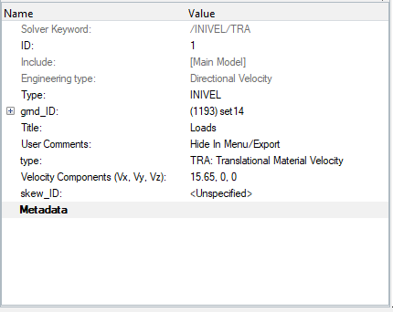
Applying initial velocity:
solver > create > boundary conditions > inivel
the velocity need to be applied is 35Mph,
since, the units are kg mm ms , thefore the value to input is 15.65mm/ms
Create appropriate interface with recommended parameters and friction force is 0.2.
Once unit system is checked. Now we have to create appropriate interface.
Therefore, in order to create the interface of Type 7, we have to display solver browser by clicking
View---->Browsers---->HyperMesh---->Solver.
Once solver browser is displayed. Now we have to create appropriate interface i.e. Type 7 with recommended parameters as shown in picture below.
Solver---->INTER---->press right click on INTER---->Select create---->TYPE7.
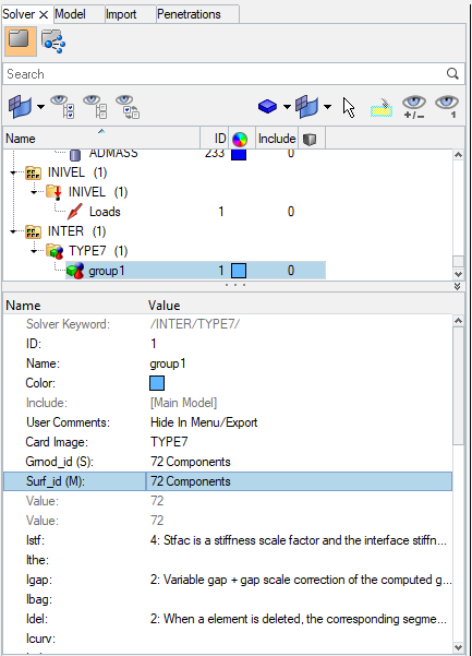
A type7 contact is created between all the 72 components with friction coefficient as 0.2,
Rigid wall (wall):
To create a rigid wall at the front side of the car, creat the outermost node at the front of the car. Using temp nodes option.
Then right-click in
solver browser and navigate to Create > RWALL > Plane
_1687962849.png)
- To apply timestep between 0.5 to 0.1 microsecond.
We have different methods to create time step such as INTER, NODA, BRICK, QUAD, SHELL, TRUSS, BEAM, SPRING etc.
And we have different time step control such as CST, CST1, CST2, DEL, STOP, AMS.
In this case we have created INTER and NODA as a type of time step control.
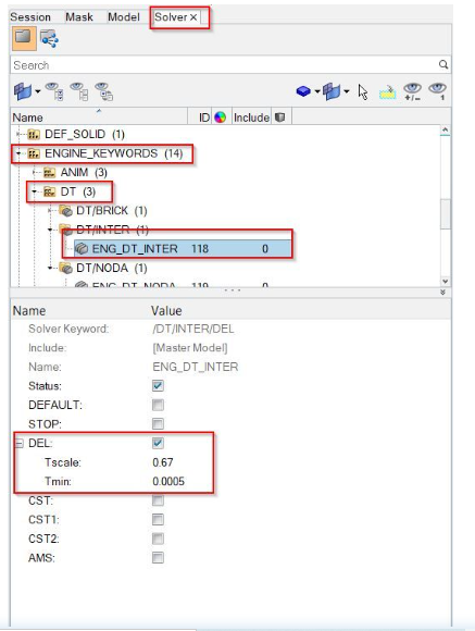
8.1. ENG_DT_INTER
This method is used in order to control the time step.
A type of time step option is “INTER” and time step control “DEL” is used.
We have to keep 0.67 as time scale factor and 0.0005 as a minimum time step control.
If time step gets reduced below the minimum time step, then this algorithm will add some mass to the element which leads to maintain time step more than minimum time step.
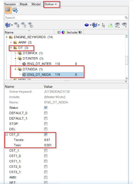
8.2. ENG_DT_NODA:
This method is used to control the time step from the nodes.
A type of time step option is “NODA” and time step control type “CST” is used.
In order to create ENG_DT_NODA we have to follow steps as explained below.
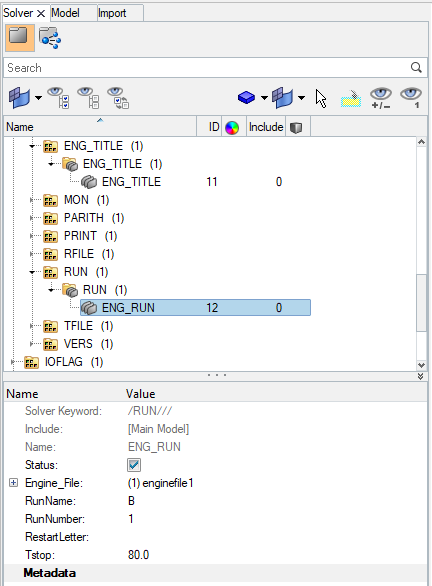
Change ENG_RUN to 80 ms
Go To Solver Tab > Cards > ENG_RUN > t.stop to 80 ms
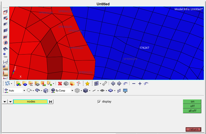
To add a sectional force in the rails at location of indicated node 174247.
First we have to display the nodes i.e. 174247. In order to display the node, we have to follow:
Tool---->numbers---->By id---->Type node number---->Display---->on.
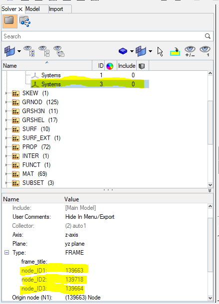
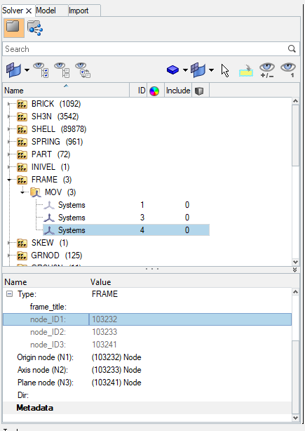
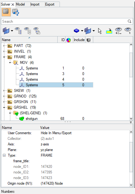
In order to create SECTION first we have to create the FRAME CARD. In this moving frame is attached with the nodes which is selected as origin.
Now, we have to create FRAME card in solver browser. In order to create FRAME card, we have to follow:
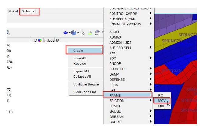
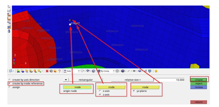
In order to assign parameters in FRAME---->MOV, we have to follow. In this we have to define origin node and then define the z-axis with second node which is in the direction of crash. And then we have to define the third node for plane as shown in picture below.
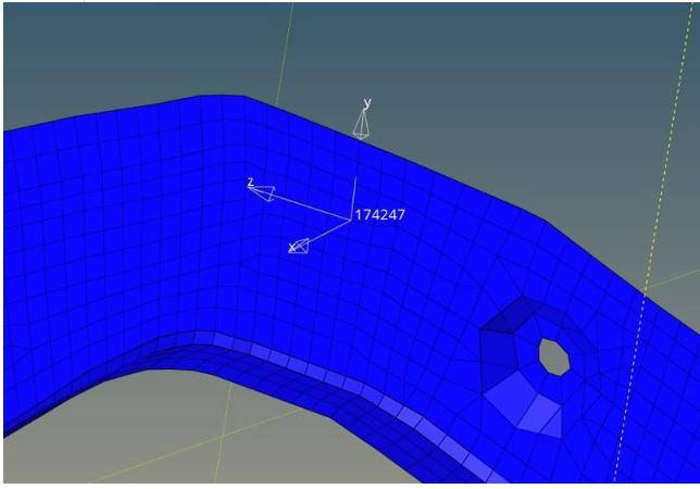
Once axis has created at node 174247, it will look like as shown in picture below.
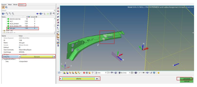
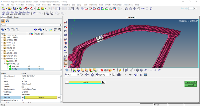
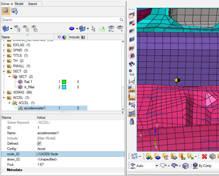
Now we have to create the SECTIONAL force at RAIL_1. In order to create SECTIONAL force we have to follow:
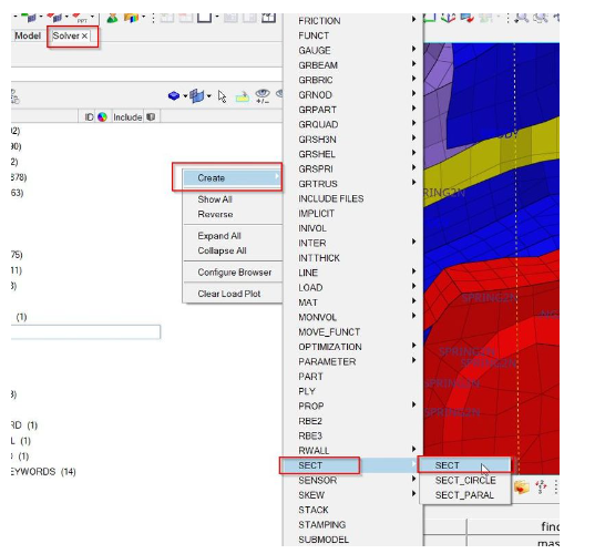
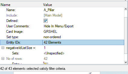
First we have to create GRSHEL card by selecting elements as shown in picture below.
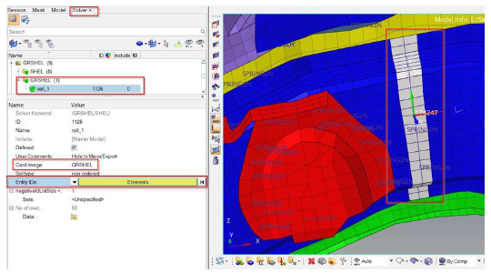
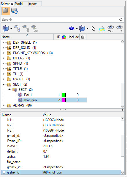
Now we have to assign this GRSHELL id in the SECT parameters as shown in picture below.
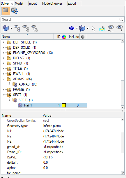
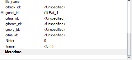
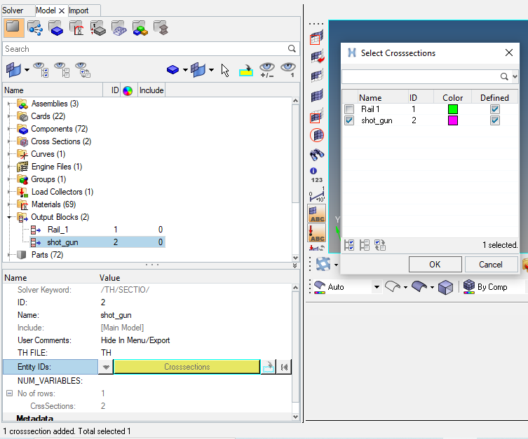
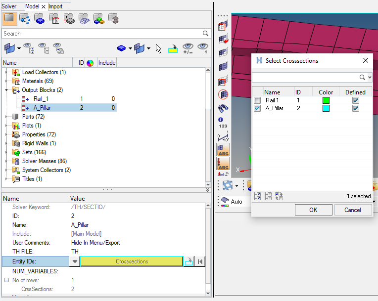
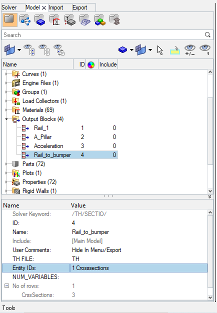
Now we have to give output blocks request in model browser as shown in picture below.
Shotgun cross sectional forces.
First we have to create a MOV collector in FRAME card as shown in picture below.
Now we have to assign GRSHELL id by selecting element as shown in picture below.
Now we have to assign parameters in SECT as shown in picture below.
Now we have to give output blocks request as shown below.
To find sectional forces in A pillar.
First we have to create a MOV collector in FRAME card as shown in picture below.
Now we have to assign GRSHELL id by selecting element as shown in picture below.
Now we have to assign parameters in SECT as shown in picture below.
Now we have to give output blocks request as shown below.
To find acceleration curve received on the accelerometer at base of B pillar (on B pillar rocker).
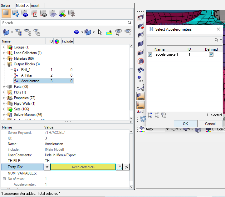
First we have to create ACCEL card in solver browser as shown below.
Now we have to give output Blocks request as shown in picture below.
To add axial force received on the rail from bumper.
First we have to create a MOV collector in FRAME card as shown in picture below.
Now we have to assign parameters in SECT as shown in picture below.
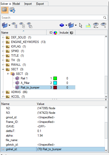
Now we have to give output blocks request as shown below.
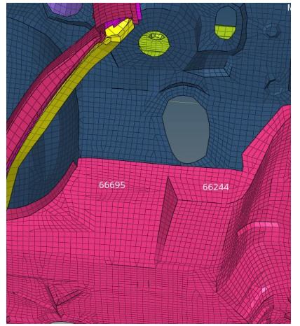
To calculate intrusions on the dash wall at node 66695 and 66244.
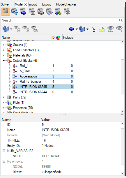
In order to show these nodes at number 66695 and 66244, we have to follow steps already explained in step 9. Once nodes are generated, it will look like as shown in picture below.
Create a node time history, select the node and assign the newly created skew to that as shown in picture below.
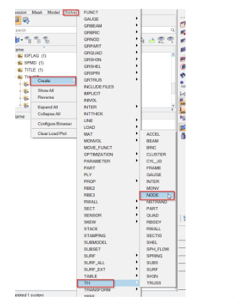
Similarly, we will do same step for node 1 and 2. Then we have to assign output blocks request for both intrusion as shown in picture below.
RUN THE ANALYSIS:
Analysis >> Radioss >> Input File: (File Location) >> Hit Radioss
The input file is the same Started file (contains model information) that we had just imported.
The animation video along with the frames will be saved in the same folder where the starter file exists.
RESULTS:
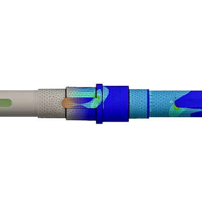
From the simulation, we can see that. Initially, the bumper starts crushing then the bumper forces are transferred to the left and right rail from the rail forces are transferred to A-Pillar LH and RH. In each stage, the forces are going to reduce because energy is absorbed in each stage.
Since this is a reduced model the car is deforming in an unrealistic manner so when the model is simulated with all the other transmission and engine components the simulation will be more realistic.
Once the simulation is run we can check the Output files for Energy errors and Mass errors.
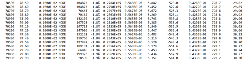
OBSERVATION:
The Energy Error is Negative and has been linearly increasing up to -1.9% only, which is acceptable. Mass error is very low which is acceptable We can conclude that the simulation is good.
Energy and Force Graphs:
The tools to plot the graph are available on Hypergraph.
Hypergraph 2D >> Data File >> FIRST_RUNT01 >> Apply
A hypergraph is a data analysis and plotting tool that represents the FEA from the simulation in graphs to the selected unit system
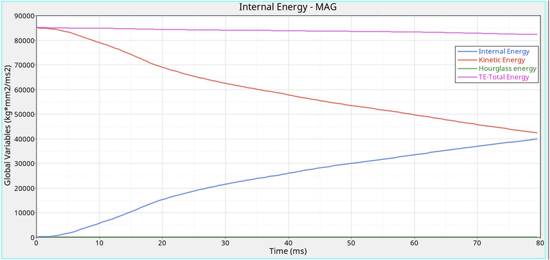
As the vehicle is moving with a certain velocity (Say 15.646 m/s for the Model), the initial kinetic Energy will be High (Refer to Above Graph). Once the car is hit by the rigid cylinder, the vehicle starts deforming results in absorbing the Surrounding Energy and stored it. Thus, internal Energy starts increasing. At the Maximum deformation, the Velocity will become Zero and thus the kinetic energy will also be dropping down to zero resulting there is no energy to absorb in the system. Thus, Internal Energy Remains Constant thereafter.
The above graph shows that the Hourglass energy is almost negligible since we have used improved integrated element formulation (QEPH).
Our Requirement from an Ideal Simulation is that we have minimal Contact energy and maximum Energy absorption/Deformation in the elements. We can check the Energy error in the Engine output file, which has maxed out at -1.9 % which is within the limits for it to be. Our Mass error is also 0 % which means that the solver did not need to add mass onto the nodes to reduce the time step to further avoid the Hourglass Error.
ENERGY PLOT:-
- As we can see, from below graph that kinetic energy is decreasing from starting time to termination time. Because a velocity is decreased over a period of time. Kinetic energy is directly proportional to velocity. Kinetic is started at 87000 and ended up with 55000.
- Internal energy is increased over a period of time. Because it has some work done in the car.
- And no hourglass energy is dissipated, since QEPH formulation has been used.
- As we know total energy is the combination of internal, kinetic energy which has been plotted below.
- Our Requirement from an Ideal Simulation is that we have minimal Contact energy and maximum Energy absorption/Deformation in the elements. We can check the Energy error in the Engine output file, which has maxed out at -1.9% which is within the limits for it to be. Our Mass error is also 0 % which means that the solver did not need to add mass onto the nodes to reduce the time step to further avoid the Hourglass Error.
- Once all parameters are filled, we have a required graph as shown in picture below.
_1688326726.png)
Dash wall intrusion at 66695 and 66244 node:
_1688326776.png)
- From the above graph, we can see that the maximum intrusion that occurred in the spring (Node 66695) during a crash is 900 mm, and the maximum intrusion that occurred in the spring (Node 66244) during a crash is 1000 mm. Practically this elongation referred to which extent the foot pedal or the passenger's legs will move once the crash is happening. From the animation, we can notice that there is deformation that occurred at this location and the elongation is also low. Hence, we can conclude that there are injuries will happen to the Passenger/driver.
SECTIONAL FORCES:
ACCELEROMETER:
_1688326882.png)
- As we all know that an Acceleration is the rate of change of velocity. To measure the acceleration, we have placed the accelerometer near the Rocker of B-Pillar as mention in question.
- Once the Car hits the rigid wall with the initial velocity, the acceleration of the vehicle during the crash is not constant across the structure. The front of the vehicle slows down immediately as it hits the rigid wall, while the rest of the structure decelerates at a slower rate as seen in the graph. As seen from the graph there is a sudden increase in the acceleration, this might be because of some vibration that occurs during the crash with respect to the point where the accelerometer is placed.
_1688326939.png)
Learning Outcome:
- Learned how to set up a frontal crash test.
- Learned how the rigid wall interface works and can lead to incompatible Kinematic conditions.
- Learned how Sectional forces are generated.
- Learned how the distribution of forces among the components during a frontal crash.
- Learned how some components are designed to deform in such a way to ensure the safety of the passengers inside the cabin.
- Learned how to Debugging errors in order to get the right results.
CONCLUSION:
The given model was simulated for the frontal crash using Radioss and the results obtained were validated. The graphical results were plotted for all the test cases. From the simulation, it can be observed that there was minimum deformation in the cabin, and also minimum intrusion was found in the driver’s seat area.
Leave a comment
Thanks for choosing to leave a comment. Please keep in mind that all the comments are moderated as per our comment policy, and your email will not be published for privacy reasons. Please leave a personal & meaningful conversation.
Other comments...
Be the first to add a comment
Read more Projects by MD SUBHAN (22)
Assignment 7-Side Pole Crash Simulation Challenge
AIM: To perform the crash on the Side body of the car to a pole and analysis where stresses are working on it. OBJECTIVES:Side Body-BIW1. Checking the unit system and either following [Mg mm s] or [Kg mm ms].2. Creating appropriate interface, friction 0.2 and recommended parameters.3. There should be no penetrations…

07 Jul 2023 03:29 PM IST
Assignment 6-Frontal Crash Simulation Challenge
Frontal Crash test AIM: Frontal car crash simulation of Dodge Neon BIW using RADIOSS solver and Preprocessing using HyperMesh / HyperCrash. OBJECTIVE: The following are the requirements for this project: Set the model of the Neon Dodge ie, the FEA model, so that the required output requests can be post-processed from it. …
02 Jul 2023 07:48 PM IST
Assignment 5-RADIOSS Interfaces & Study of Effect of Notches Challenge
AIM: To study the RADIOSS Interfaces and the effect of notches using Hypermesh, Hyperview and Hypergraph 2D. OBJECTIVES OF THE PROJECT: To create mesh for bumper assembly, mesh element size is 6mm. To apply and study the different cases for the crash tube model. To study the effect of notches on the crash tube. To plot…
25 Jun 2023 09:25 PM IST
Assignment 4-RADIOSS Material Laws Challenge
AIM: To run crash analysis on the given model by applying different materials laws available in Radioss and post-process the results Objective: To carry out simulations of the given starter files and compare the results. There shall be 7 cases (according to given parameters) and they are to be compared primarily via animations…
20 Jun 2023 08:27 PM IST
Related Courses


Skill-Lync offers industry relevant advanced engineering courses for engineering students by partnering with industry experts.


Our Company

4th Floor, BLOCK-B, Velachery - Tambaram Main Rd, Ram Nagar South, Madipakkam, Chennai, Tamil Nadu 600042.

Top Individual Courses
Top PG Programs
Skill-Lync Plus
Trending Blogs
© 2025 Skill-Lync Inc. All Rights Reserved.