


Courses by Software
Courses by Semester
Courses by Domain
Tool-focused Courses
Machine learning
POPULAR COURSES
Success Stories

Week 8 - Challenge 3 - Coin Holder Design
AIM Create the Coin Holder Plastic component through the given Class-A surface.the tooling axis for the given Class-A Surface should be created meeting the requirements of the draft angle and at the end perform the Draft analysis on the model. the Thickness of the component to be 2.5 mm REPORT CLASS A SURFACE In automotive…
Karthik S
updated on 08 Dec 2022


AIM
Create the Coin Holder Plastic component through the given Class-A surface.the tooling axis for the given Class-A Surface should be created meeting the requirements of the draft angle and at the end perform the Draft analysis on the model. the Thickness of the component to be 2.5 mm
REPORT
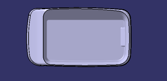
CLASS A SURFACE
In automotive design, a class A surface is any of a set of free form surfaces of high efficiency and quality. It gives the aesthetic of the component which is created by the styling team and gives to the part design engineer to create the part with all engineering aspects.
We have been given the Class-A surface and the first thing to do is to make sure that the given surface has no gap in between them. We can check it visually and also with help of Join or boundary commands.
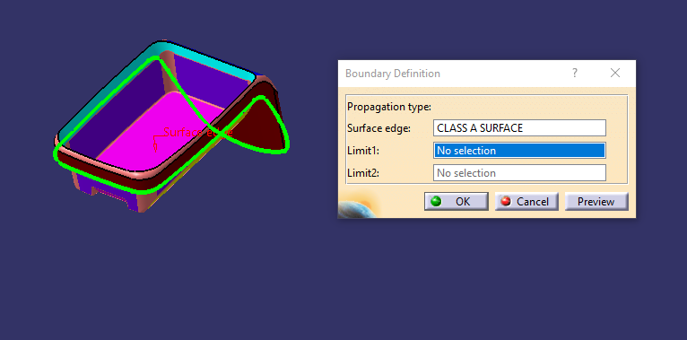
The given surface has one boundaries which are one outer boundary. So, there are no other gaps found.
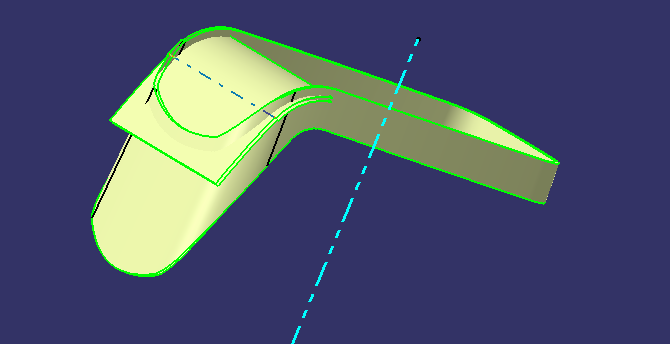
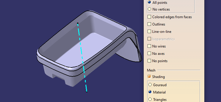
TOOLING AXIS
The direction in which the mold or core and cavity opens is the tooling axis.
Dummy tooling axis
By checking the all three axis the best tooling direction is determined.

there is bin shaped area and wall around it .it is a major consideration for dummy tooling axis.the walls are almost 90 degree to surface. so the tolling axis should be perpendicular to flat base of bin area
created point on extracted base surface and a perpendicular line is drawn and Dummy tooling axis created

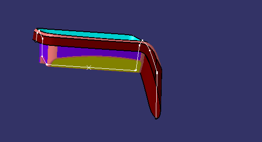
TOOLING AXIS USING BISECTING METHOD
Tooling axis for the part is created by using the dummy tooling axis using the bisectiong method .In order to check whether the part is toolable in the direction,the class A surface is analysed and the walls which are doubtful of clearing the 3 degree draft angle to the dummy tooling axis is identified.
an axis system is created on point to take intersection

first intersection is taken on yz axis

lines are drawn atthe walls which are almost parallel to dummy tooling axis

bisecting lineis drawn to this two lines

second intersection is taken along xy axis

lines are drawn atthe walls which are almost parallel to dummy tooling axis

bisecting lineis drawn to this two lines

TOOLING AXIS is created by bisecting the axis created on two intersections which is same as dummy tooling axis

DRAFT ANGLE
When developing parts for plastic injection molding, applying a draft (or a taper) to the faces of the part is critical to improving the moldability of your part. Without it, parts run the risk of poor cosmetic finishes and may bend, break, or warp due to molding stresses caused by plastic cooling. Equally important, an absence of draft may prevent parts from ejecting from the mold, damaging not only the parts but possibly the mold itself—a costly and time-consuming detour.
DRAFT ANALYSIS OF CLASS A SURFACE
Change the view to material mode for draft anlysis

draft analysis is done using featured draft analysis tool
Use the compass fucnction to aling the compass to the tooling direction and lock the direction using lock function in the draft analysis tool bar

the surface is showing green colour so that the surface clears the minimum draft angle of 3 degree

By using the analyses under the running pointwe can check draft angle on the individual faces. It shows how much draft on specific points when we move the cursor point.

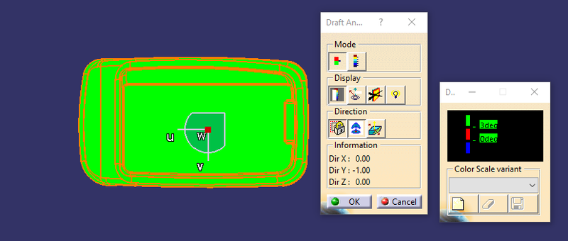

Green colour - above 3 degree positive draft
Red colour -between 3 and 0
orange colour- below 0 degree

CLASS B SURFACE
CLASS B SURFACE
Class-B surface means the thickness of a part it is not visible and is inside part. In other words, the Class-B surface is a surface below a certain thickness from the class-A surface. This is the surface that contains engineering aspects of a model.The Class B finish is a quality finish with only minimal imperfections. A Class B finish is the most common finish for exterior surfaces. It is normally specified on surfaces such as external covers, panels, and parts that are fairly prominent.
BASE
extracted the surface

untrim the surface

Extrapolate the surface


Trim the surface


offset to the thickness

BASE is created
SIDE WALLS
extracted the surface

untrim the surface

Extrapolate the surface

Trim the surface

offset to the thickness

Fillet is provided and SIDE WALL is created

TOP WALL
extracted the surface

Extrapolate the surface

offset to the thickness

extracted the surface

untrim and Extrapolate the surface

offset to the thickness

OUTER FLANGE
extracted the surface

Extrapolate the surface

untrim the surface

Extrapolate the surface

Join the surface

offset to thickness
splitthe surface for trimming

trimming the surface

Join the surface and OUTER FLANGE is created

FINAL TRIM


Fillet is provided

CLASS B SURFACE is created
CLASS C SURFACE
The surface that joins class-A and class-B surfaces are class-C surfaces. Class C is often specified for interior surfaces not readily visible, surfaces that will be covered by another part when assembledThe Class C finish allows more imperfections than Class A or B. Class C is often specified for interior surfaces not readily visible, surfaces that will be covered by another part when assembled, or surfaces which the Customer feels do not need to meet a high cosmetic finish.
CLASS C SURFACE
The first step is to create the boundary of the CLASS-A surface
boundary is extracted

reference curve is extracted

c surface is created is using sweep function

C SURFACE IS CREATED

COMPONENT
trim class B and Class C

Join with class A

COMPONENT IS CREATED
TREE STRUCTURE


PART BODY
Close Surface feature usedto make a solid body from the surface


DRAFT ANALYSIS OF COMPONENT
Change the view to material mode for draft anlysis
draft analysis is done using featured draft analysis tool
Use the compass fucnction to aling the compass to the tooling direction and lock the direction using lock function in the draft analysis tool bar

the surface is showing green colour so that the surface clears the minimum draft angle of 3 degree

By using the analyses under the running pointwe can check draft angle on the individual faces. It shows how much draft on specific points when we move the cursor point.

Green colour - above 3 degree positive draft
Red colour -between 3 and 0
blue colour- below 0 degree


CONCLUSION
- Created the Coin Holder component using the given Class-A surface.
- the tooling axis for the given Class-A Surface is created which meeting the requirements of the draft angle
- Draft analysis is done on the CLASS A surface
- Draft analysis is done on the model.
- Using the Close Surface feature solid body is created from the surface
- Publications: Tooling Axis Class A, B, and C surface and closed surface
Leave a comment
Thanks for choosing to leave a comment. Please keep in mind that all the comments are moderated as per our comment policy, and your email will not be published for privacy reasons. Please leave a personal & meaningful conversation.
Other comments...
Be the first to add a comment
Read more Projects by Karthik S (27)
Project 2
AUTOMOTIVE WIRING HARNESS BACKDOOR Statement of assignment: Route the Wiring harness on Given car body and Prepare flatten view drawing in CATIA V5. Application of all Packaging rules, Industry best practices studied in this course shall be demonstrated in design. Apply Protection coverings as required. Available connector…

24 May 2023 03:20 PM IST
Project 1
AIM Route the Wiring harness on Given Engine and Prepare flatten view drawing in CATIA V5. Application of all Packaging rules, Industry best practices studied in this course shall be demonstrated in design. Apply Protection coverings as required. ENGINE WIRING HARNESS ROUTING …
23 May 2023 03:27 PM IST
Wiring harness design in CATIA V5 - 3D modeling Week 7 Challenge
AIM: TO FLATTEN THE WIRING HARNESS AND DRAFT THE WIRING HARNESS ASSEMBLY. GIVEN: HARNESS ASSEMBLY: HARNESS FLATTENING: WE GO TO THE HARNESS FLATTENING WORKBENCH AND DEFINE THE FLATTENING PARAMETERS. WE USE THE EXTRACT COMMAND TO BRING THE HARNESS ASSEMBLY TO THE FLATTENING WORKBENCH HERE. CHOOSING A SUITABLE PLANE WE FLATTEN…
13 May 2023 09:10 AM IST
Wiring harness design in CATIA V5 - 3D modeling Week 5 & 6 Challenge
modelling Week 5 & 6 Challenge Aim: Route two electrical harnesses per the given layout and interconnect them as a single harness assembly check for bundle continuity, and bundle warnings, and then provide annotations for the final harness assembly. Objective: The objective of this project is to first route the two Harness…
12 May 2023 08:28 AM IST
Related Courses


0 Hours of Content
Skill-Lync offers industry relevant advanced engineering courses for engineering students by partnering with industry experts.


Our Company

4th Floor, BLOCK-B, Velachery - Tambaram Main Rd, Ram Nagar South, Madipakkam, Chennai, Tamil Nadu 600042.

Top Individual Courses
Top PG Programs
Skill-Lync Plus
Trending Blogs
© 2025 Skill-Lync Inc. All Rights Reserved.