


Courses by Software
Courses by Semester
Courses by Domain
Tool-focused Courses
Machine learning
POPULAR COURSES
Success Stories

Week 8 - Challenge 2 - Switch Bezel Design
Aim: This project aims to create a switch bezel plastic component using the given class A surface following the OEM standard. and perform the draft analysis. Class A-surface Objective: Ensure Proper Tree Structure. Geometrical sets should have a proper name based on the sketches present inside them. All the sketches…
Karthik S
updated on 07 Dec 2022


Aim: This project aims to create a switch bezel plastic component using the given class A surface following the OEM standard. and perform the draft analysis.
Class A-surface

Objective:
- Ensure Proper Tree Structure.
- Geometrical sets should have a proper name based on the sketches present inside them.
- All the sketches should be created under the Geometrical set.
- Use the Close Surface feature to make a solid body from the surface.
- To publish the Tooling Axis, Class A, B, and C surface.
Introduction:
CLASS-A SURFACE: the class-A surface is used in the automotive design industry. it describes the final production surface data for the aesthetic parts.
CLASS-B SURFACE: the class-B surface is the second surface that has a certain thickness from the class-A surface. this surface contains engineering aspects of a model. These must be smooth and "error-free" as well but are not held to the standards that class A surfaces are.
CLASS-C SURFACE: The Class C finish allows more imperfections than Class A or B. Class C is often specified for interior surfaces not readily visible, surfaces that will be covered by another part when assembled, or surfaces.
Design methodology:
Insert the class A surface of the switch bezel in CATIA software.
Determining the tooling axis for the switch bezel
Creation of class B surface.
Creation of class c surface.
Join the switch bezel's class A, class B, and class c surfaces and ensure all the surfaces are closed surfaces.
Use the Close Surface feature to make a solid body from the surface.
finally, Perform the Draft analysis on the switch bezel final plastic component.
Creating tooling axis:
The ejection from the mold after manufacturing the interior trim must have the nominal 3-degree draft angle.
hence the tooling directions created by considering the above factor and bisecting method is used.
The base surface of the class-A was extracted to create a reference point on the surface using the point, create a line in the z-direction and an axis system was inserted to the point
then using projection intersection along the yz plane is created and the two inclined lines were drawn inside the positioned sketch.
then bisecting lines with the two inclined lines were created.

Now the same procedure is done along the xz plane but on xz plane, we only have one surface line so the center point is used to extrude a line along the z-direction and gave a measurement of 6 degrees. from the surface line.

Bisecting these two lines sketch1 and sketch2 the bisecting line is created and published as a tooling axis.


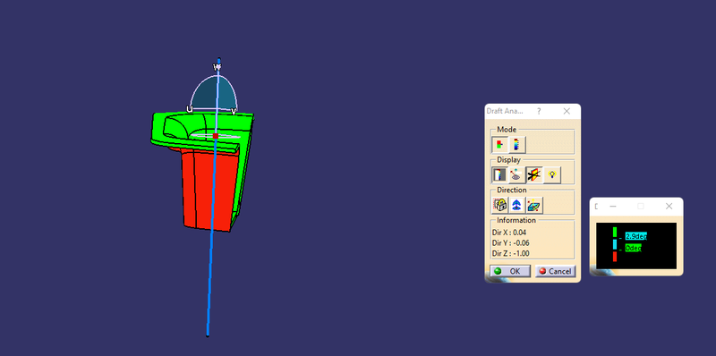
DRAFT ANALYSIS ON CLASS-A SURFACE:
- Go to insert> analysis> feature draft analysis
- Align the tooling axis with the compass.
- Click on the surface and see that the surface is within the permissible limit of the draft values.
- The surface should be green and in the column nominal value 3deg given as input. hence the draft analysis on the class-A surface is successfully performed.

CLASS-B SURFACE CREATION: divide the class-A surface into 3 different surfaces as shown below.

working on these surfaces one by one we have to follow the same procedure for the 1-bezel rest surface, 2-base, and 3-walls.
The first step is to Extract the surfaces untrim and extrapolate the surfaces
Offset the surfaces (by measuring the thickness) here the input is given as 2.5mm
1-bezel rest surface

2-Base

3-walls


once all the surfaces are created (i.e, bezel rest surface, walls, and base surface). The required trim operations were performed to form a class-B surface

To Perform the fillet operation. Fillet value should be calculated from the Class A surfaces for every edge in the B surface.
The fillet value should be calculated to ensure the component has a uniform thickness.

Class-A and Class-B surface

CLASS-C SURFACE CREATION:
The edges of the Class-A surface are extracted using the multiple extracts and then converted into smooth curvature to avoid the patches.


Sweep operation is performed (with draft direction) selecting the smooth curves as the guide curve and tooling axis as the direction and draft angle as 3deg

join class-A and class-C surfaces. Make sure that there is no unnecessary boundary present, if there is then increase the merging distance to not more than 0.003mm. and even after there is some unwanted boundary, extrapolate class-A by a small distance and trim it with class-c instead of joining them.


Then trim the class-C surface with the class-B surface.

THE CLASS-C SURFACE

Go to the part workbench by using the Close Surface feature we created a solid body from the surface.

Switch Bezel Final Plastic Component:

DRAFT ANALYSIS OF FINAL PLASTIC COMPONENT:
Following the similar steps performed for draft analysis of class-A surface, we obtained the following result

The draft analysis command enables you to detect if the part you drafted will be easily removed. This type of analysis is performed based on color ranges identifying zones on the analyzed element where the deviation from the draft direction at any point, corresponds to specified values.
by selecting the tooling axis, class A class B and class C surface publish it by going to menu bar> tools> publication. this will be published under the publication tab in a tree structure.
ISOMETRIC VIEW

FRONT VIEW

SIDE VIEW
TOP VIEW

FEATURE TREE


 .
.
RESULT:
Switch Bezel plastic component using class-A surface successfully created and performed the draft analysis on the class-A surface and final plastic component.
Leave a comment
Thanks for choosing to leave a comment. Please keep in mind that all the comments are moderated as per our comment policy, and your email will not be published for privacy reasons. Please leave a personal & meaningful conversation.
Other comments...
Be the first to add a comment
Read more Projects by Karthik S (27)
Project 2
AUTOMOTIVE WIRING HARNESS BACKDOOR Statement of assignment: Route the Wiring harness on Given car body and Prepare flatten view drawing in CATIA V5. Application of all Packaging rules, Industry best practices studied in this course shall be demonstrated in design. Apply Protection coverings as required. Available connector…

24 May 2023 03:20 PM IST
Project 1
AIM Route the Wiring harness on Given Engine and Prepare flatten view drawing in CATIA V5. Application of all Packaging rules, Industry best practices studied in this course shall be demonstrated in design. Apply Protection coverings as required. ENGINE WIRING HARNESS ROUTING …
23 May 2023 03:27 PM IST
Wiring harness design in CATIA V5 - 3D modeling Week 7 Challenge
AIM: TO FLATTEN THE WIRING HARNESS AND DRAFT THE WIRING HARNESS ASSEMBLY. GIVEN: HARNESS ASSEMBLY: HARNESS FLATTENING: WE GO TO THE HARNESS FLATTENING WORKBENCH AND DEFINE THE FLATTENING PARAMETERS. WE USE THE EXTRACT COMMAND TO BRING THE HARNESS ASSEMBLY TO THE FLATTENING WORKBENCH HERE. CHOOSING A SUITABLE PLANE WE FLATTEN…
13 May 2023 09:10 AM IST
Wiring harness design in CATIA V5 - 3D modeling Week 5 & 6 Challenge
modelling Week 5 & 6 Challenge Aim: Route two electrical harnesses per the given layout and interconnect them as a single harness assembly check for bundle continuity, and bundle warnings, and then provide annotations for the final harness assembly. Objective: The objective of this project is to first route the two Harness…
12 May 2023 08:28 AM IST
Related Courses


Skill-Lync offers industry relevant advanced engineering courses for engineering students by partnering with industry experts.


Our Company

4th Floor, BLOCK-B, Velachery - Tambaram Main Rd, Ram Nagar South, Madipakkam, Chennai, Tamil Nadu 600042.

Top Individual Courses
Top PG Programs
Skill-Lync Plus
Trending Blogs
© 2025 Skill-Lync Inc. All Rights Reserved.