What does the PG program in bridge design teach, and in what order?
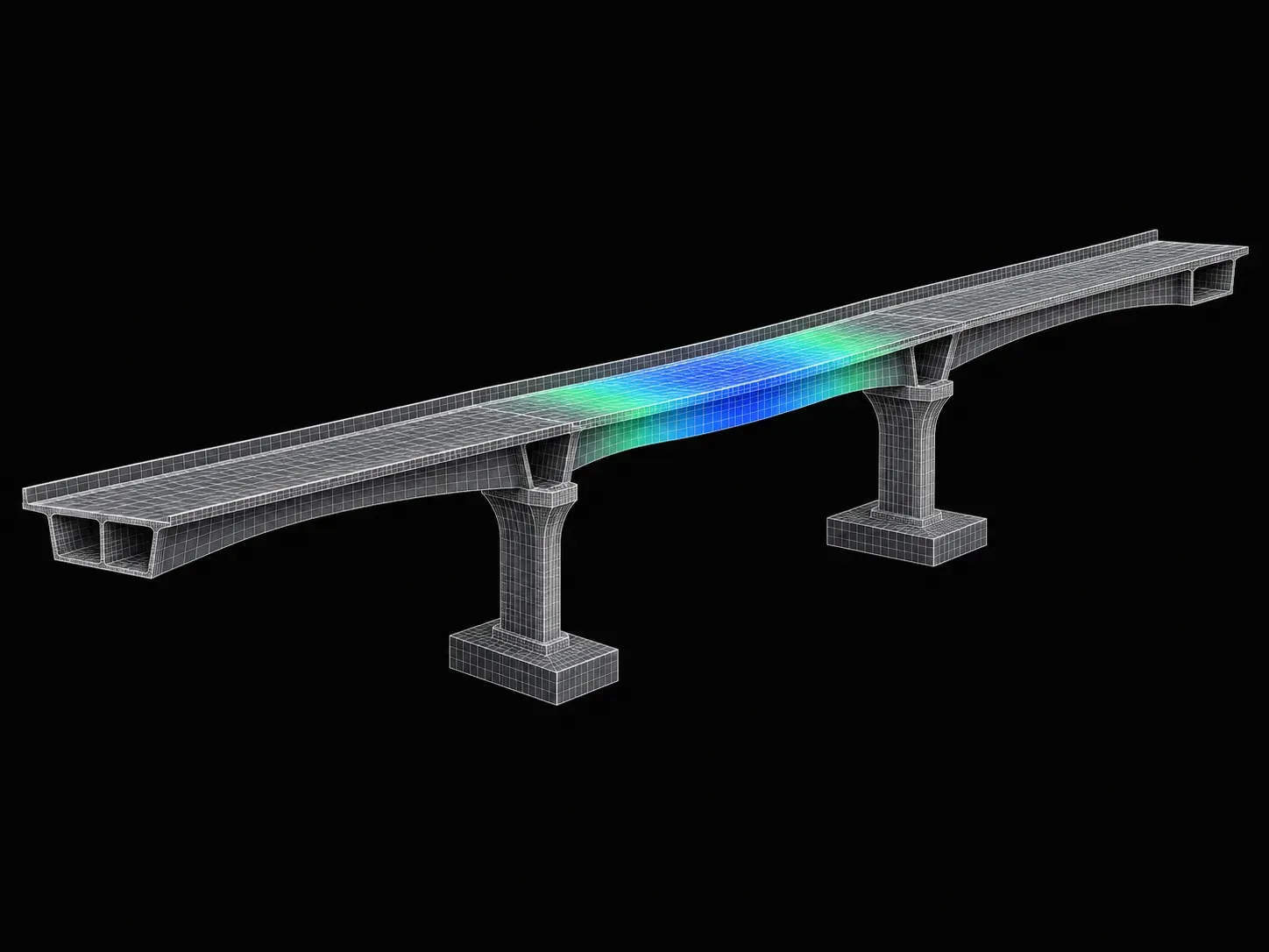
It follows a road or metro bridge from the loads on it, down through the piers to the foundations, in six STAAD.Pro courses. Steel superstructures and the seismic design of bridges complete it. Each course has two projects, the program runs 48 weeks online, and Autodesk Structural Bridge Design is used for capacity checks.
The courses, in the order the syllabus lists them (lesson counts and hours come from each course's video list):
- Design Loads considered on Bridges using STAAD.Pro (25 lessons, about 10 hours). One load a week: dead load, IRC road and IRS rail live loads, earth pressure, wind, seismic, water current, centrifugal and impact, waves, snow, temperature, then shrinkage, vehicle collision and barge impact.
- Design of Bridge Foundations using STAAD.Pro (54 lessons, about 23 hours). Shallow foundations, site parameters, abutments and piers on open foundations, rafts, then deep foundations: stability checks, piles and wells.
- Design of Elevated Metro Viaducts using STAAD.Pro (about 20 hours). One viaduct from top to bottom: prestressed open web structures and I-girders, bearings, PSC and RCC pier caps, the pier, the pile cap, piles, and open and well foundations.
- Design of Bridge Substructures / Piers using STAAD.Pro (45 lessons, about 21 hours). Bearings and articulation, pier caps, corbels, a full bridge model with load combinations, capacity checks in Autodesk Structural Bridge Design, and RC detailing.
- Design of Steel Superstructure for Bridges using STAAD.Pro (44 lessons, about 16 hours). Conceptual design, analysis, construction stages, truss bridges, plate girder bridges and steel composite bridges.
- Seismic Design and Analysis of Bridges using STAAD.Pro. Ground motions, structural dynamics, IS 1893 and IRC 6, seismic design of the substructure and foundation, and two worked bridges: a single-span integral bridge and a multiple-span bridge.
The projects include a raft foundation for a box bridge, a pile foundation for an RCC slab bridge, the I-girder superstructure of a metro viaduct, a portal pier, the substructure of a 5-span box girder bridge, and a steel composite bridge sized from a riverbed contour map. Five of the six courses also have their own course pages, and the bridge design courses page lists them side by side.
What are the parts of a bridge, and which course covers each?
A bridge has three main parts. The superstructure (the deck and girders) carries the traffic, the substructure (piers, pier caps and abutments) holds it up, and the foundation passes everything into the soil. Bearings sit between deck and substructure. Each part has its own course in this program.
Think of a table carrying a tray. The tray is the deck, the legs are the piers, and the floor under the legs is the foundation. The bearings are the felt pads under the tray: they pass the weight down but let the tray slide a little as it warms and cools.
- Superstructure. Steel truss, plate girder and composite decks are in the steel superstructure course. Prestressed I-girders and open web girders for metro lines are in the viaduct course. Concrete slab and box decks in LUSAS are a separate course, not part of this program.
- Bearings. Week 1 of the substructures course (bearings and articulation, meaning which bearings are fixed and which slide) and week 6 of the viaduct course.
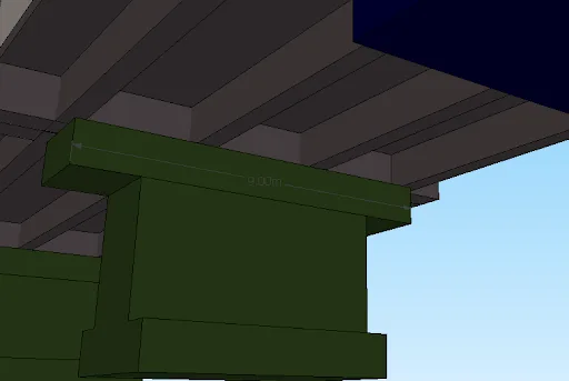
- Substructure. An abutment is the end support that also holds back the approach embankment. A pier is an intermediate support, and its pier cap is the wide beam on top that collects the bearings. These are the substructures course, plus weeks 7 to 9 of the viaduct course.
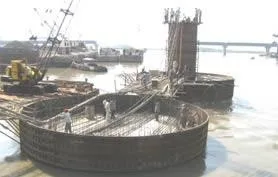
- Foundation. An open foundation is a shallow footing or raft on firm ground. A pile foundation pushes columns of concrete deep into the ground. A well foundation is a large hollow caisson sunk into a riverbed. All three are in the foundations course and weeks 10 to 12 of the viaduct course.
The free lessons explain the order of work plainly. A bridge is built from the bottom up: foundation, then substructure, then deck. It is designed from the top down, because the deck's loads have to be known before the pier and foundation can be sized. They also explain scour, soil washed away from around a foundation by the river, which is why river foundations go deep, and the rule of thumb the course uses for a shallow foundation: depth no more than its breadth. A pile that rests on rock is an end-bearing pile; one that holds by the grip of the soil along its length is a friction pile.
What loads does IRC:6 put on a road bridge?
IRC:6 sets the standard vehicles a road bridge must carry, plus the extra for their dynamic effect (impact), braking, wind, temperature, water current, earth pressure, earthquake and more. The two vehicle loadings most designs meet are the Class A train of vehicles and the heavier Class 70R. The figures below are from IRC:6-2017.
IRC has issued amendments to IRC:6-2017 since, so check the current amended copy before you design with any of these numbers.
- Class A (Fig. 2) is a train of a truck and two trailers on eight axles: 2.7, 2.7, 11.4, 11.4, 6.8, 6.8, 6.8 and 6.8 tonnes, spaced 1.1, 3.2, 1.2, 4.3, 3.0, 3.0 and 3.0 m. That is 55.4 t over 18.8 m. Each Class A train takes one lane, and successive trains are at least 18.5 m apart, nose to tail.
- Class 70R (Fig. 1) comes in two forms. The wheeled vehicle is 100 t on seven axles (8, 12, 12, 17, 17, 17 and 17 t). The tracked vehicle, which runs on two tracks like a tank, is 70 t spread over 4.57 m. It needs a carriageway of at least 5.3 m and takes two lanes. Clause 201.1 says a bridge designed for 70R must be checked for Class A too, because Class A can give higher stresses.
- Impact (clause 208). A truck bouncing over a joint presses down harder than a parked one, so the live load is raised by a fraction. For Class A on spans of 3 to 45 m:
IRC=6+L4.5Isteel=13.5+L9with L the span in metres. For a 20 m span that is 4.5/26 = 17.3% for a concrete bridge and 9/33.5 = 26.9% for a steel one. Fig. 9 flattens the curves at 50% and 54.5% for spans of 3 m or less, and at 8.8% and 15.4% for 45 m or more. For a tracked 70R vehicle on a concrete span of 9 to 40 m, the allowance is a flat 10%.
- Braking (clause 211.2). On a one- or two-lane bridge, 20% of the first train plus 10% of any trains behind it, in one lane only. A full Class A train gives 0.2 × 55.4 t = 11.08 t, about 108.7 kN, acting 1.2 m above the road (211.3). It is not raised for impact.
- Wind and earthquake have their own clauses (209 for wind). Amendment No. 3 of May 2018 replaced the seismic clause of IRC:6-2017 with a reference to IRC:SP:114, the separate guidelines for seismic design of road bridges.
Load factors. For strength checks, Table B.2 multiplies dead load by 1.35, surfacing by 1.75, and the leading live load by 1.5 (1.15 when it accompanies another leading load such as wind). The design loads course spends one week on each of these loads.
How do you find the maximum live-load moment in a bridge girder? A worked example with Class A
Roll the vehicle across the span and record the bending moment under each axle at every position; the largest value wins. For one lane of IRC Class A on a 20 m simply supported span, the peak is 151.4 t·m (about 1,485 kN·m), under the second 11.4 t axle, 11.12 m from a support. With 17.3% impact it is 1,742 kN·m.
The tool behind this is the influence line: a graph of the moment at one point as a single 1 t load moves across the span. For a point at distance z on a span L, a load at q gives q(L−z)/L when it is left of the point and z(L−q)/L when it is right of it. Multiply each axle by its ordinate and add. Because the graph peaks under the point, the maximum always sits under an axle.
Hand calculations use the c.g. rule: put the span's midpoint halfway between a heavy axle and the resultant (the centre of gravity) of the loads on the span. Here that places the second 11.4 t axle at 11.12 m, with seven axles on the span and the last 6.8 t axle just off it. The whole 55.4 t train fits on 20 m, yet loading all of it gives only 135.3 t·m. The heavy axles matter more than the total weight. The search, in Python:
P = [2.7, 2.7, 11.4, 11.4, 6.8, 6.8, 6.8, 6.8]  # axle loads, t (Fig. 2)
gap = [1.1, 3.2, 1.2, 4.3, 3.0, 3.0, 3.0]  # axle spacings, m
L = 20.0  # simply supported span, m
x = [sum(gap[:i]) for i in range(len(P))]  # offsets behind front axle
best = (0, 0)
for k in range(int((L + x[-1]) * 100) + 1):  # roll on in 1 cm steps
    on = [(p, k / 100 - xi) for p, xi in zip(P, x) if 0 <= k / 100 - xi <= L]
    for z in [q for _, q in on]:  # the peak sits under an axle
        M = sum(p * (q * (L - z) if q <= z else z * (L - q)) / L for p, q in on)
        best = max(best, (M, z))
M, z = best
I = 4.5 / (6 + L)  # impact, RC bridge, clause 208.2
print(f"{M:.1f} t.m at {z:.2f} m, {M * 9.81:.0f} kN.m, with impact {M * 9.81 * (1 + I):.0f}")
# 151.4 t.m at 11.12 m, 1485 kN.m, with impact 1742
Times the 1.5 load factor, the lane's design moment is 2,613 kN·m. That is per lane, not per girder. How a deck shares one lane among its girders is a separate step, and in practice STAAD.Pro's moving-load generator does this rolling for you. The substructures course has lessons titled "Creating Class A Vehicle Loadings in STAAD.Pro" and "Maximum Load Generation and Envelope Options in Moving Load Analysis". This script is the hand check that tells you whether the software's answer is sensible.
How is the load shared between the piles under a bridge pier? A worked example
Treat the pile cap as rigid. Each pile takes an equal share of the vertical load, plus or minus a share of each moment in proportion to its distance from the centre of the group. For an assumed six-pile group under 7,200 kN, the corner pile carries 1,510 kN and the opposite corner 890 kN.
Picture four people carrying a table. Put a box in the middle and each takes a quarter. Slide the box toward one end and the two at that end take more. The moment at the base of a pier, from braking, wind and off-centre traffic, is that slide. The formula (the rigid cap method, the one STAAD Foundation Advanced documents) is:
Qi=nP+∑y2MLyi+∑x2MTxiwith xi and yi the signed distances of pile i from the centre of the group. Assumed values: six 1.2 m piles in two rows of three, spaced 3.6 m (three diameters) both ways. Service loads at the underside of the pile cap: vertical P = 7,200 kN, longitudinal moment ML = 2,000 kN·m, transverse moment MT = 1,800 kN·m. The safe capacity of one pile, which in practice comes from the soil investigation, is taken as 1,500 kN.
- P/n = 7,200/6 = 1,200 kN.
- Rows at ±1.8 m: ∑y2 = 6 × 1.8² = 19.44 m², so ML adds ±2,000 × 1.8/19.44 = ±185.2 kN.
- Columns at −3.6, 0 and +3.6 m: ∑x2 = 4 × 3.6² = 51.84 m², so MT adds ±1,800 × 3.6/51.84 = ±125.0 kN to the outer piles.
The worst corner takes 1,200 + 185.2 + 125.0 = 1,510 kN, 10 kN over capacity. Spreading the outer piles to 4.2 m drops it to 1,492 kN. The least-loaded pile stays in compression, so no pile is pulled out of the ground. The check, in Python:
P, ML, MT = 7200.0, 2000.0, 1800.0  # kN, kN.m (assumed service loads)
def piles(sx, sy=3.6):  # 3 piles across at sx, 2 rows sy apart, m
    pts = [(x, y) for x in (-sx, 0, sx) for y in (-sy / 2, sy / 2)]
    Iy = sum(x * x for x, _ in pts)
    Ix = sum(y * y for _, y in pts)
    return [P / len(pts) + ML * y / Ix + MT * x / Iy for x, y in pts]
for sx in (3.6, 4.2):
    Q = piles(sx)
    print(f"{sx} m: max {max(Q):.0f} kN, min {min(Q):.0f} kN")
# 3.6 m: max 1510 kN, min 890 kN
# 4.2 m: max 1492 kN, min 908 kN
The wider cap is heavier, so a real design adds its extra weight and checks again. The pile itself still needs its own checks: its capacity from the soil, its reinforcement, and the sideways load from braking and earthquake. Those are weeks 7 to 11 of the foundations course and week 11 of the viaduct course.
Can I try the program before enrolling? What do the free lessons teach?
Yes. Nine lessons from three bridge courses are free to watch. Three come from the foundations course, three from the substructures course, both part of this program, and three from the separate LUSAS concrete deck course. They are the opening lessons of each course, so they show the level and the teaching style before you pay.
- Bridge foundations, free lessons: bridge types by superstructure and material; bridge functions, location studies (hydrology, soil investigation, earthquake zone) and the main components; and why bridges need foundations, with scour and the shallow versus deep choice. The instructor names IRC 6, IRC 78 and IRC 112 as the codes the course follows.
- Bridge substructures, free lessons: how bridges are classified; the parts of a bridge, the design codes, and minimum concrete and steel grades; and the loads on a bridge with the IRC 6 ultimate limit state table. We checked the factors it ends on (dead load 1.35, surfacing 1.75, leading live load 1.5) against Table B.2 of IRC:6-2017.
- RCC and PSC decks in LUSAS, free lessons: concrete and steel basics, the cracking moment and ultimate capacity of a concrete beam worked in Excel, and how span and site decide a concrete bridge form. This course is not part of the program; take it on its own if you want concrete deck design.
The remaining lessons are locked. Their titles show where the courses go next, for example "Pier Caps in Bridge Construction", "Corbels and Their Design", "Crack Width Analysis" and "Understanding Scour and Its Impact on Foundations: Calculation and Liquefaction Insights".
What jobs do learners from this program get?
Our data here is thin. As of 20 Nov 2026, Skill-Lync has only 4 placement records filed under this program, from 2022 (1) and 2023 (3). That is too few for a typical salary. Three disclosed pay, from ₹1.4 to 8 LPA. The titles are trainee bridge engineer, bridge or assistant engineer, and design engineer.
The employers were RD Civil Solutions (2), WSP and MAPS Global Civiltech. Across all programs, 4 records have "bridge" in the job title, and 3 of them are from this program. Completing the program does not guarantee a bridge design job.
These figures come from Skill-Lync's placement records (n = 3,905 across all programs). They are a self-reported learner sample, mostly 2021 to 2023 starting offers, so treat them as a starting point, not a promise. See civil engineer salaries for a wider view, and the bridge design course comparison for other options, including free ones.
Which Skill-Lync bridge design course fits you?
| Course | Length | Projects | Tools | Fee |
|---|
| PG Program in Bridge Design and Analysis (this page)48 weeks, 6 courses: loads to foundations, STAAD.Pro | 48 weeks, 89 h | 14 | STAAD.Pro, Autodesk Structural Bridge Design | ₹2,75,000 |
| Design loads considered on bridgesIRC and IRS bridge loads, one per week, in STAAD.Pro | 12 weeks, 10 h | 2 | STAAD.Pro | ₹40,000 |
| Design of Bridge Foundations using STAAD.ProOpen, raft, pile and well foundations for bridges | 12 weeks, 23 h | 2 | STAAD.Pro | ₹40,000 |
| Design of Bridge Substructures / Piers using STAAD.ProPiers, pier caps, corbels, checks in ASBD | 11 weeks, 21 h | 2 | STAAD.Pro, Autodesk Structural Bridge Design | ₹40,000 |
| Design of Elevated Metro Viaducts using STAAD.ProOne metro viaduct: girders, bearings, piers, piles | 12 weeks, 20 h | 2 | STAAD.Pro | ₹40,000 |
| Design of RCC and PSC Superstructures using LUSASRCC and PSC concrete decks in LUSAS (not in the PG) | 12 weeks, 23 h | 2 | LUSAS | ₹40,000 |
Lengths, projects and fees are taken from each course page on 20 Nov 2026; fees are the Premium plan in INR, including all charges.